
Do you know what is a RC2014?
It is a simple 8 bit Z80 based modular computer designed by Spencer Owen in the UK. It is inspired by the home built computers of the late 70s and computer revolution of the early 80s. It is not a clone of anything specific, but there are suggestions of the ZX81, UK101, S100, Superboard II and Apple I. It nominally has 8K ROM, 32K RAM, runs at 7.3728MHz and communicates over serial at 115,200 baud.
As it is modular you can create (or buy) new modules (boards) and incorporate those into the computer backplane, then create software to use them. As a bare minimum, a RC2014 has a CPU, ROM, RAM, Clock and Input/Output modules.
It is a great tool if you really want to understand how a computer works, how the diverse architectural components interact, or if you just want to thinker around electronics, hardware and software in general. I got one a few weeks ago and as I’m on (stay)cation during two weeks I had time to assemble and play with it.
You can buy a RC2014 kit from Tindie or directly from Spencer on https://z80kits.com. The official website for the RC2014 is https://rc2014.co.uk/
Assembly
The assembly is pretty straightforward. You just need a solder iron and patience.
Mine is a RC2014 classic II and it came in a small box. I also selected the option to get the Digital IO board as well. That board has a set of 8 leds and input buttons so I could create cool interactive programs for the computer.


The boards were made for someone with no experience with soldering and the instructions available on the website are very good. You just need to follow those and after a few hours you will have everything in place.
Remember you need to check for any bridges and clean the flux with alcohol after soldering so you don’t get any shorts when powering your RC2014 on.
Playing with it
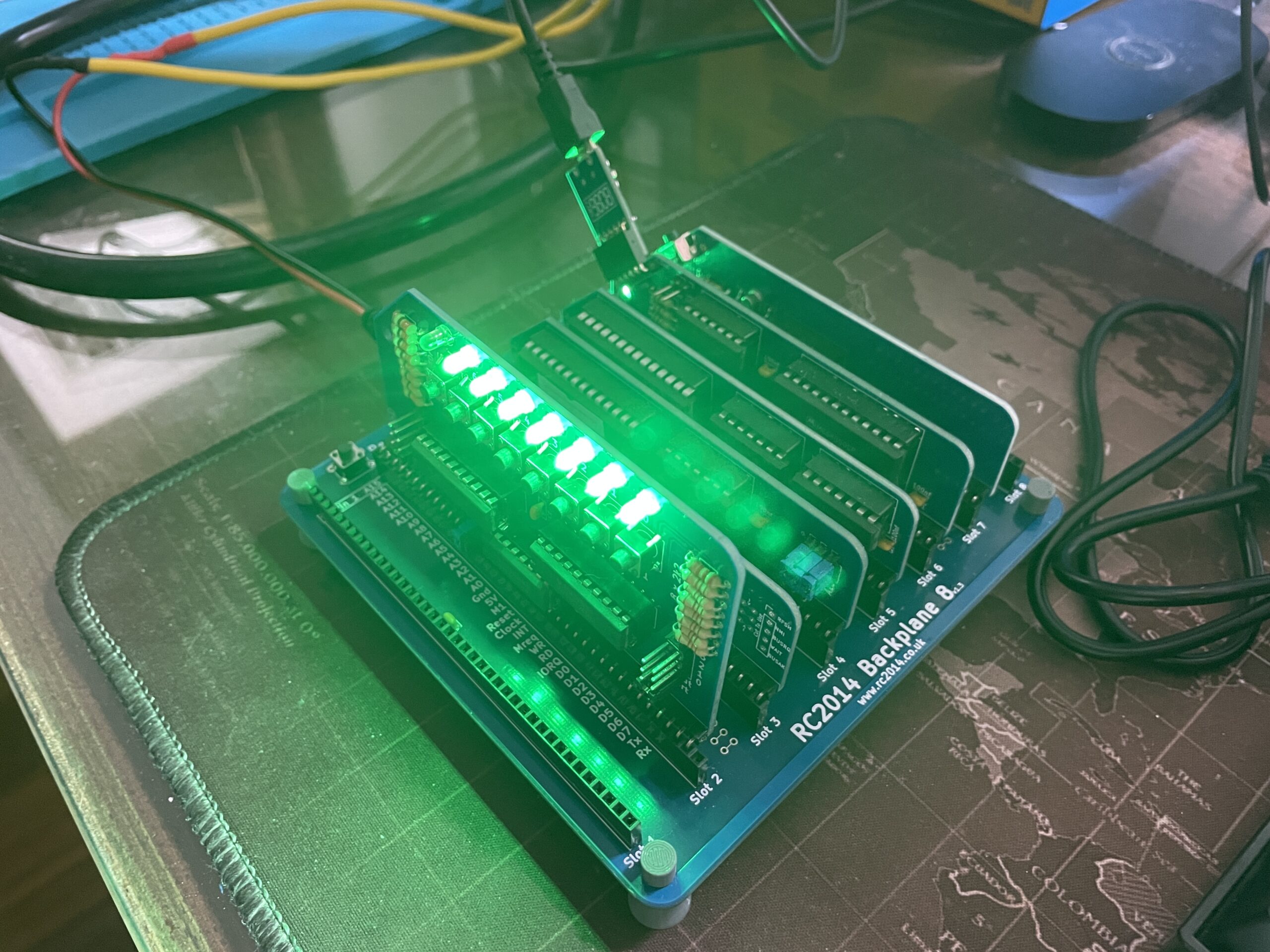
With all the modules ready I connected them to the backplane with the Clock and Reset module on slot 7, then Digital IO, CPU, ROM, RAM, and Serial IO to slots 2 to 6.
As part of the kit I also got a FTDI to USB adapter and that was good as I figured out my FTDI cable can’t work with Windows 11. I had it for long time and apparently it uses a PL2303 chip from Prolific that is not supported anymore on recent versions of Windows. So my tip for you is to get the adapter together with the kit so you don’t give any chances to end up fighting with drivers for your OS.


I’m using my bench power supply to provide 5V center positive to the board and because of that I’m not using the jumper located on the Serial IO module. Then I connected the USB cable to the FTDI adapter and configured Putty to connect to the newest COM port on my computer (115200bps, 8N1).

I had to click on the reset button and get the default RC2014 screen shown below (left side). Then after an Enter I got access to basic. Nice… no smoke of death from any of the boards.


Software
Now it is time to create software for the unit. Checking Philip Stevens GitHub repo I found a Mandlebrot fractal code in basic and that was the first thing running on my RC2014.


Let’s play with the Digital IO board.
After testing a few simple things like lighting up leds when pushing the buttons, creating a binary display program and then playing around with the classic Larson Scanner implementation I decided to jump ahead and implement the RC2014 version of the Simon memory game.
I would say playing with 8 green leds instead of 4 colorful ones it is a bit more challenging, but that is a cool way to use the Digital IO board.
Here is a video of myself playing Simon with the RC2014. Just 3 rounds to keep the video short :). How cool is that?
I uploaded all the code I used for my tests, including the Simon memory game to a new RC2014 dedicated GitHub repo. If you have a RC2014 or if you are planning to buy one to play and thinker, feel free to use the source code.
See you next time…
Stay safe, Cristiano.