
This is the first post of the Let’s Build series. My intention is to share not only posts related to Microsoft software but also general technology subjects.
My kids are avid Minecraft players, they do advanced stuff on the game and discuss things that I don’t really understand. Just for fun I decided to print and “light-up” a Minecraft lamp for them. The goal is to 3D print a cool one available on Thingiverse and use an Arduino together with a small piece of a WS2812B addressable LED strip to create cool colorful effects from inside the lamp.

Bill of Materials
Here is a list with everything you going to need. Links provided are not sponsored and for your reference only. They usually provide more than you need for the project (you can always use material for the future ones):
- 1 x Sparkfun Arduino Pro Micro compatible board (5V version) – You can use any Arduino board; I’m using the pro micro due its size and because I had a few here on my parts bin. [AliExpress]
- 1 x WS2812B 5V LED strip piece (with 16 LEDs) – I had a big strip and I just cut 16 leds from it to use on the project. [AliExpress]
- 1 x Push Button [AliExpress]
- Thermo retractable isolation tube or isolation tape [AliExpress]
- Electronic wires [AliExpress]
- 1 x 3 pin connector male and 1 x 3 pin connector female (optional, in case you want to make the led strip removable from the Arduino board) [AliExpress]
- Solder Iron kit [AliExpress]
- 1 x Micro USB cable (usually those come together with the Arduino board or you may have some already)
- Cyanoacrylate glue [AliExpress]
Those are very easy to find directly from AliExpress or your choice of maker/electronics shop. Be aware that you need a 5V LED strip and not a 12V one. 12V LEDs are much easier to find and cheaper but can’t be used in our project without an additional circuit.
3D Print
The original lamp project was created by Jörgen Pehrson and can be found here. I based mine on a remix created by Adam Stanczak and available here. Adam made a change to Jörgen project to include the appropriate mount for the LED stripe instead of the LED ring used originally.
I printed the lamp body in standard black PLA and the light diffusers in white PLA using my Creality Ender 3D v2 printer.


In total we have 5 pieces and a base where we will mount the Arduino board and the stand for the LED lights (they are all designated in the project). We also need to print the stand in black and 5 light diffusers in white so we can create a nice effect. Those diffusers will be glued from the inside with the cyanoacrylate glue.


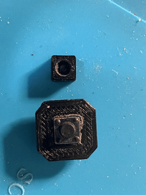
To finish the printing job, you will need to print the button support and cap. That will be the place where you mount the push button so it can be glued into the lamp and be used from outside.
Circuit
The idea behind the circuit with Arduino is read a push button and cycle between the various sequences we will program for the LED strip.
Push Button
When using a push button with Arduino, the recommendation is always put a resistor to clear the input and ensure that you will always present a defined state (0 or 1) to the micro controller input, otherwise the input could be left floating (which is unwanted).
The resistor is kind of mandatory for proper operation of the push button. However, there is a little secret embedded in each Arduino pin. Each pin already has a pull-up resistor that we can enable with just one small change in our code.
We just need to initialize the pin that will be used by the button with INPUT_PULLUP and connect it to GND and the input pin. We will do it for the sake of simplicity and to avoid the use of a resistor in the lamp.
LED Strip
We will be using a WS2812B LED strip for this project. The WS2812B addressable LED strip comes in several models that differ in size, sealant or LED density. The LED strip is made by WS2812B LEDs wired in series with an IC built in, allowing communication via a one-wire interface. That means that we can control the LEDs using just one digital pin of our Arduino.
I’m using a WS2812B with a density of 60 LEDs per meter. I adjusted the size of it cutting a piece containing 16 LEDs. We make a few changes on that piece and glue it to the support we printed previously.


That is to make easier to mount the lights into the mount when building the lamp. You just need to cut 6 pieces of electronics wire and solder those into the LED strip contacts appropriately.
I also used the thermo-retractable isolation tube to protect the area where I soldered the wires into the strip.


There is a whole discussion around the use of a capacitor and another resistor as well as the use or not of the Arduino 5V line to power up the LED stripe.
The strip is connected to the circuit using GND, 5V and a specific pin we will use to control it. I used a connector have flexibility.
The whole circuit is shown below.

I did use a protoboard to test the circuit before mount it to the lamp. I also uploaded the Arduino code to the board to test the effects and decide the best colors with my kids.


The following pictures show the strip and the board mounted on the base of the lamp.


Here is the video of the building process for the whole lamp. I’m not the best person in craft and managing the glue, but at the end I got something at least capable to stand alone.
Arduino Code
The code is very simple and use Arduino interruptions to flag a variable that is checked in every effect cycle. When you push the button, the variable is flagged and on the start of the next cycle the following effect is going to be selected. I use a mod operation to have a circular selection among the multiple effects starting with blank, then red, blue, green, rainbow and then strobe lights.
I’m using Platform IO Visual Studio code extension to create the code, but you can use the Arduino IDE with no problems. You just need to configure the FastLED library, remove the #includes and configure the Sparkfun Arduino pro micro board over there.
If using Platform IO, you need to following the steps below:
- Connect the micro USB cable to the Arduino board.
- Open Visual Studio code, click on the Platform IO icon on the left rail and create a new project called Minecraft Lamp clicking on “+ Create New Project”. If you don’t have Platform IO installed you need to click Extensions, search for Platform IO and click Install.

- You need to select the Sparkfun Pro Micro 5V/16MHz board and the Arduino framework.

- Now you need to download and associate the FastLED library to your project. Click Libraries and then Search for FastLED.
- Click on FastLED and then click Add to Project.

- Select the Minecraft Lamp project from the dropdown and click Add.

- Click on the VSCode file explorer and expand the src folder. Click on the main.cpp file and paste the code below.
#include <Arduino.h>
#include <FastLED.h>
#define NUM_LEDS 16 //number of LEDs on the strip
#define DATA_PIN 3 //strip data pin
#define BUTTON 2  //pin connected to the button
#define CTLMAX 6 //number of sequences to execute on the led stripe
int CTLCNT = 0;   //sequence control
int CTLEXC = -1;   //current sequence to execute
int buttonState = 0; //button state
int buttonToggle = false;
CRGB leds[NUM_LEDS]; // Define the array of leds
void buttonPressed()
{
  buttonToggle = true;
}
void fadeall() { for(int i = 0; i < NUM_LEDS; i++) { leds[i].nscale8(250); } }
void sequence0()
{
  FastLED.clear();  //clear all pixel data
  FastLED.show();   //activate the LED strip
}
void sequence1() //red
{
	for( int colorStep=0; colorStep<256; colorStep++ ) {
      int r = colorStep;      // Redness starts at zero and goes up to full
      int b = 0;              // Blue starts at full and goes down to zero
      int g = 0;              // No green needed to go from blue to red
      // Now loop though each of the LEDs and set each one to the current color
      for(int x = 0; x < NUM_LEDS; x++){
          leds[x] = CRGB(g,r,b);
      }
      // Display the colors we just set on the actual LEDs
      FastLED.show();
      delay(10);
  }
  for( int colorStep=255; colorStep>=0; colorStep-- ) {
      int r = colorStep;      // Redness starts at zero and goes up to full
      int b = 0;  // Blue starts at full and goes down to zero
      int g = 0;              // No green needed to go from blue to red
      // Now loop though each of the LEDs and set each one to the current color
      for(int x = 0; x < NUM_LEDS; x++){
          leds[x] = CRGB(g,r,b);
      }
      // Display the colors we just set on the actual LEDs
      FastLED.show();
      delay(10);
  }
}
void sequence2() //blue
{
  for( int colorStep=0; colorStep<256; colorStep++ ) {
      int r = 0;      // Redness starts at zero and goes up to full
      int b = colorStep;  // Blue starts at full and goes down to zero
      int g = 0;              // No green needed to go from blue to red
      // Now loop though each of the LEDs and set each one to the current color
      for(int x = 0; x < NUM_LEDS; x++){
          leds[x] = CRGB(g,r,b);
      }
      // Display the colors we just set on the actual LEDs
      FastLED.show();
      delay(10);
  }
  for( int colorStep=255; colorStep>=0; colorStep-- ) {
      int r = 0;      // Redness starts at zero and goes up to full
      int b = colorStep;  // Blue starts at full and goes down to zero
      int g = 0;              // No green needed to go from blue to red
      // Now loop though each of the LEDs and set each one to the current color
      for(int x = 0; x < NUM_LEDS; x++){
          leds[x] = CRGB(g,r,b);
      }
      // Display the colors we just set on the actual LEDs
      FastLED.show();
      delay(10);
  }
}
void sequence3() //green
{
  for( int colorStep=0; colorStep<256; colorStep++ ) {
      int r = 0;      // Redness starts at zero and goes up to full
      int b = 0;  // Blue starts at full and goes down to zero
      int g = colorStep;              // No green needed to go from blue to red
      // Now loop though each of the LEDs and set each one to the current color
      for(int x = 0; x < NUM_LEDS; x++){
          leds[x] = CRGB(g,r,b);
      }
      // Display the colors we just set on the actual LEDs
      FastLED.show();
      delay(10);
  }
  for( int colorStep=255; colorStep>=0; colorStep-- ) {
      int r = 0;          // Redness starts at zero and goes up to full
      int b = 0;          // Blue starts at full and goes down to zero
      int g = colorStep;  // No green needed to go from blue to red
      // Now loop though each of the LEDs and set each one to the current color
      for(int x = 0; x < NUM_LEDS; x++){
          leds[x] = CRGB(g,r,b);
      }
      // Display the colors we just set on the actual LEDs
      FastLED.show();
      delay(10);
  }
}
void sequence4() //rainbow
{
  static uint8_t hue = 0;
	// First slide the led in one direction
	for(int i = 0; i < NUM_LEDS; i++) {
		// Set the i'th led to red
		leds[i] = CHSV(hue++, 255, 255);
		// Show the leds
		FastLED.show();
		// now that we've shown the leds, reset the i'th led to black
		fadeall();
		// Wait a little bit before we loop around and do it again
		delay(50);
	}
	// Now go in the other direction.
	for(int i = (NUM_LEDS)-1; i >= 0; i--) {
		// Set the i'th led to red
		leds[i] = CHSV(hue++, 255, 255);
		// Show the leds
		FastLED.show();
		// now that we've shown the leds, reset the i'th led to black
		// leds[i] = CRGB::Black;
		fadeall();
		// Wait a little bit before we loop around and do it again
		delay(50);
	}
}
void sequence5() //strobe
{
  int r = 255;
  int g = 255;
  int b = 255;
  for(int j = 0; j < 10; j++) {
    for(int x = 0; x < NUM_LEDS; x++){
          leds[x] = CRGB(g,r,b);
    }
    FastLED.show();
    FastLED.clear();  // clear all pixel data
    FastLED.show();
    delay(50);
  }
  delay(500);
}
void setup() {
  Serial.begin(9600); //debug
  attachInterrupt(digitalPinToInterrupt(BUTTON),buttonPressed,CHANGE); //interrupt handling
  FastLED.addLeds<WS2812B, DATA_PIN, RGB>(leds, NUM_LEDS);  // GRB ordering is typical
  FastLED.setBrightness(100);
  FastLED.clear();  //clear all pixel data
  FastLED.show();   //activate the LED strip
  pinMode(BUTTON, INPUT_PULLUP); //configure the button input pin to use the pull-up resistor)
}
void loop() {

  if (buttonToggle)
  {
    buttonToggle = false; //reset the button toggle
    Serial.print("SEQUENCE: "); //debug
    CTLEXC = CTLCNT % CTLMAX; //calculates the mod to get the current sequence
    Serial.println(CTLEXC); //debug
    CTLCNT++; //increment the sequence control
    FastLED.clear();   // clear all pixel data
    FastLED.show();   //activate the LED stripe
  }
  //execute the sequences based on CTLEXC
  switch(CTLEXC) {
      case 0: //call sequence 0
        sequence0();
        break;
      case 1: //call sequence 1
        sequence1();
        break;
      case 2: //call sequence 2
        sequence2();
        break;
      case 3: //call sequence 3
        sequence3();
        break;
      case 4: //call sequence 4
        sequence4();
        break;
      case 5: //call sequence 5
        sequence5();
        break;
    };
  delay(300); //delay
}
- Click on the Platform IO icon on the left rail and then hit Upload. Wait until the code is compiled and uploaded to the Arduino board.
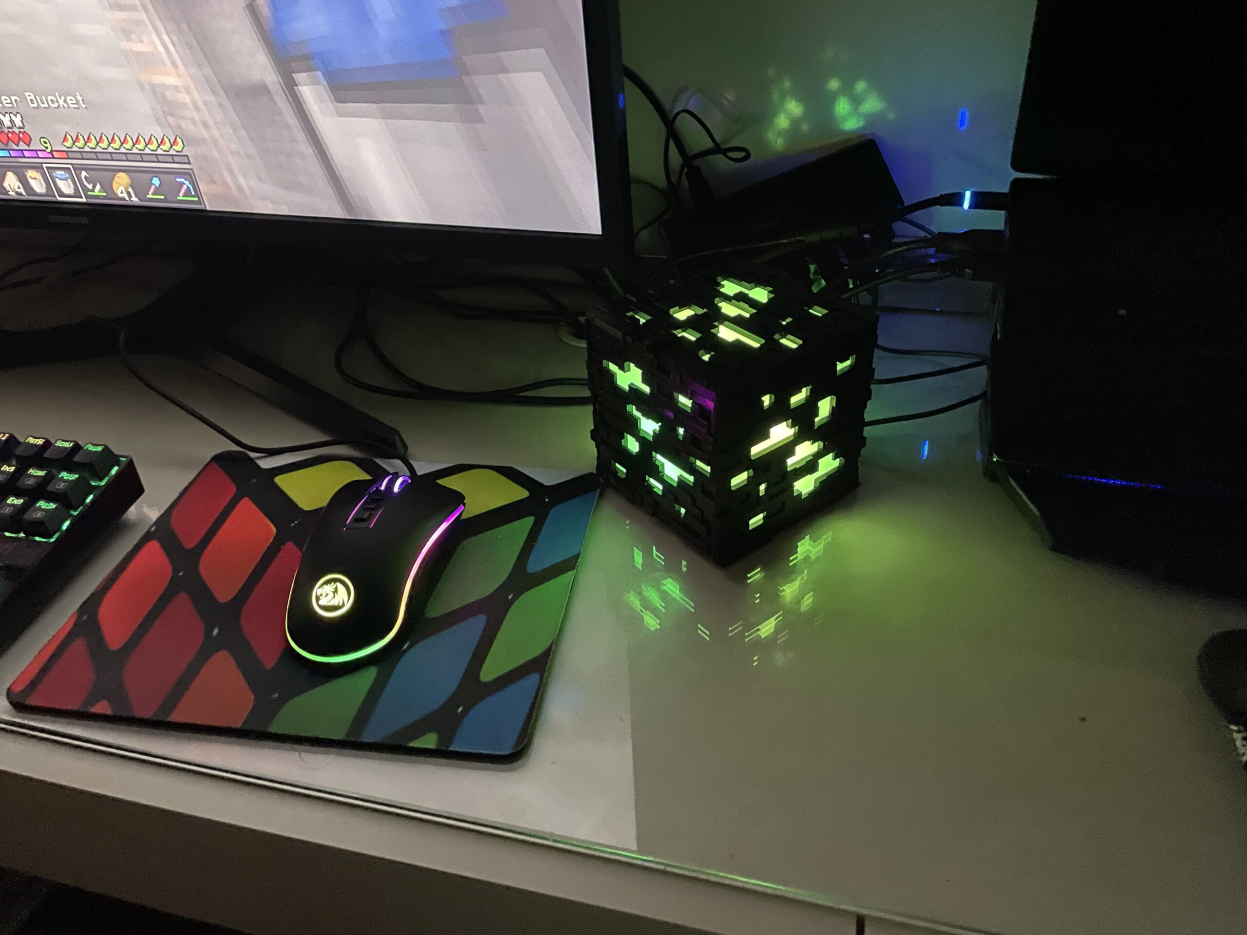
Final product
Here are pictures of the final product in action.


And finally a picture of the happy owner. Reach him on his youtube channel here. Live longer and prosper!

Variations
With the same code you can also create variations of the Minecraft Lamp. I created the headphone stand below with the same approach and code.


This web site definitely has all of the information and facts I needed about this subject and
didn’t know who to ask.