
MSX computers hold a significant place in computing history, and their legacy continues to be celebrated through innovative approaches like FPGA synthesis. Field-Programmable Gate Arrays (FPGAs) provide a unique platform for recreating the MSX architecture, offering a flexible and efficient way to re-create the hardware.
This synthesis enables enthusiasts to experience the charm of MSX systems without relying on original, often scarce, hardware components. FPGA-based MSX simulations can faithfully replicate the distinctive features of these iconic computers, including the Z80 processor, graphics capabilities, and sound architecture.
This modern approach not only preserves the nostalgia associated with MSX but also opens up possibilities for enhancements and customizations. FPGA synthesis ensures that the MSX spirit endures, catering to both seasoned aficionados and new generations eager to explore the roots of personal computing.
WARNING! If you intend to use this project to implement your own hardware, remember as per the license you must release the modified files under the same license. I’ve seen multiple projects based on files I publish on Github that were never released to the public, and I think that’s a shame (and of course a violation of the license!).
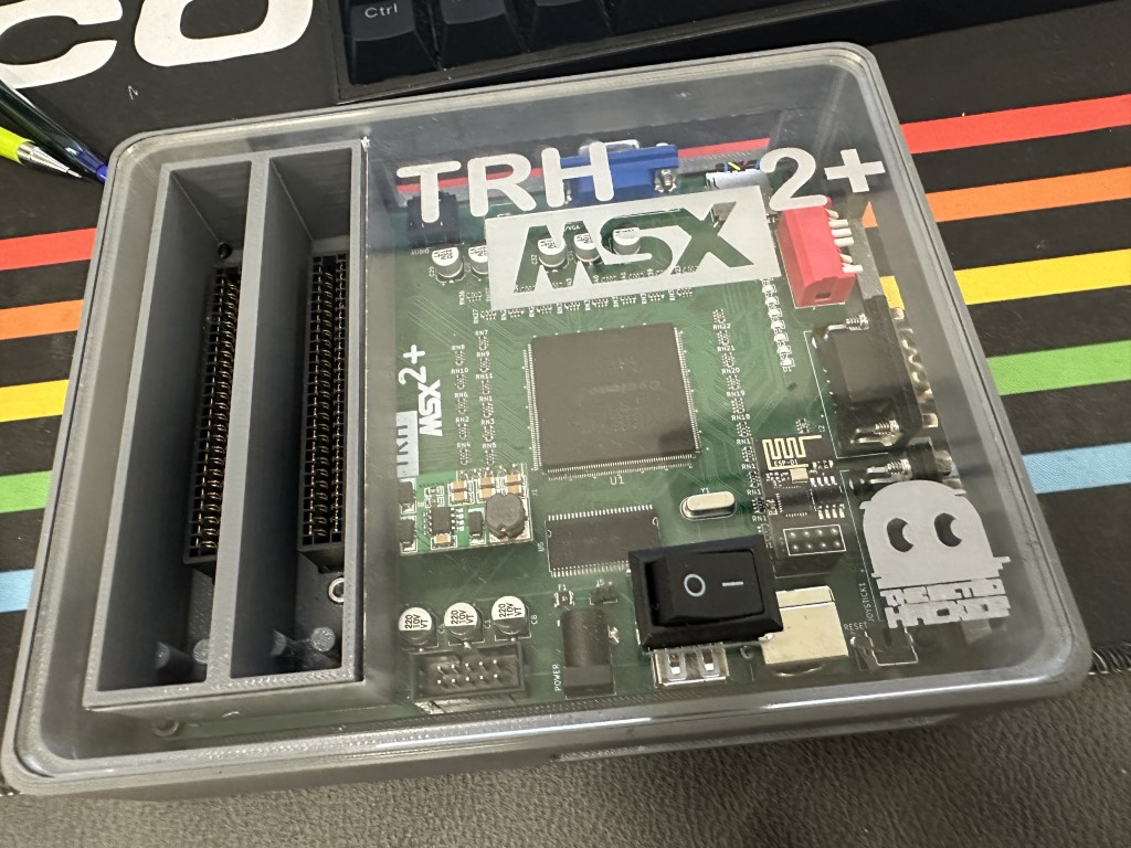
The TRHMSX – A simple FPGA MSX2+ clone
This FPGA-based MSX2+ hardware represents a simple implementation of the MSX2+ standard, drawing inspiration from the original 1chipMSX circuit but featuring several enhancements and a new PCB design for improved functionality. Despite its advanced capabilities, the primary focus during development was on maintaining a low-cost solution.
The core of this system is the Cyclone I FPGA, accompanied by a few additional components. The PCB is a 4-layer board measuring 12×15 cm. The FPGA is a 240-pin package, which is challenging to solder manually. Instead, using an SMT oven or a hot air station is advised for optimal results. For those opting for a hot air station, employing a stencil to apply solder paste is highly recommended, significantly streamlining the assembly process.


Programming the FPGA requires the well-known KDL ESE MSX2+ core, available for download [here](https://gnogni.altervista.org/). This core ensures the proper functioning of the MSX2+ hardware, providing users with a reliable and authentic MSX experience on this FPGA-based system.
Features
- MSX2+ Compatibility: Reproducing the MSX2+ architecture, ensuring compatibility with a wide range of software and games.
- Expanded Memory Options: Choose between 2MB or 4MB of mapped RAM, providing users with flexibility for diverse computing needs and applications.
- 9958 Video Display Processor (VDP): Incorporating the 9958 VDP for sharp graphics and improved visual performance, delivering an authentic MSX experience.
- FM and SCC Sound Capabilities: Featuring FM synthesis and SCC sound to reproduce the iconic audio characteristics of MSX systems, enhancing the overall gaming and multimedia experience.
- Programmable Sound Generator (PSG): Including the original PSG for standard MSX audio output.
- Keyboard Compatibility: Supporting PS/2 keyboards with the option for USB keyboards, providing users with a choice for their preferred input device.
- MicroSD Card Support: Integrating a microSD card slot for convenient storage and easy access to files, games, and software.
- MSX Cartridge Slots: Equipped with two MSX cartridge slots, allowing users to explore a vast library of MSX cartridges for an extended range of applications and games.
- Dual Joystick Ports: Featuring two joystick ports for multiplayer gaming and compatibility with classic MSX peripherals.
- Wireless Network Support: Incorporating wireless network support through the ESP8266, enabling online connectivity and expanding the possibilities for networked applications.
- 12V Cartridge Lines: Providing dedicated 12V lines for cartridges, ensuring compatibility with a variety of peripherals and accessories.
Bill of Materials

The interactive BOM can be found here. Click on the GitHub icon above to access the repository with all required files.
| Reference | Value | Description | Qty | Link |
| TRHMSX PCB | N/A | Custom Printer Circuit Board for the TRHMSX 1.0 | 1 | PCBWay |
| U1 | EP1C12Q240C8N | FPGA Cyclone Family 12060 Cells 275.03MHz 130nm Technology 1.5V 240-Pin PQFP | 1 | AliExpress |
| RN27, RN28, RN29, RN30, RN31, RN32, RN33, RN34 | 200R | 0603X4 200R Resistor Array | 8 | AliExpress |
| RN1, RN2, RN3, RN4, RN5, RN6, RN7, RN8, RN9, RN10, RN11, RN13, RN14, RN15, RN16, RN19, RN20, RN21, RN22, RN23, RN36, RN37, RN38, RN39, RN40, RN41, RN42, RN43 | 100R | 0603X4 100R Resistor Array | 28 | AliExpress |
| RN12, RN25, RN26, RN35, RN44 | 10KR | 0603X4 10K R Resistor Array | 5 | AliExpress |
| RN17, RN18, RN24 | 1KR | 0603X4 1K R Resistor Array | 3 | AliExpress |
| C2, C3, C4, C6, C7, C9, C10, C11, C12, C15, C16, C17, C18, C19, C20, C21, C22, C23, C24 | 0.1uF | 0805 100nF Ceramic Capacitor (104) | 19 | AliExpress |
| C13, C14 | 27pF | 0805 27pF Ceramic Capacitor (270) | 2 | AliExpress |
| C26, C27 | 4.7uF | 0805 4.7uF Ceramic Capacitor (475) | 2 | AliExpress |
| C25 | 2.2uF | 0805 2.2uF Ceramic Capacitor (225) | 1 | AliExpress |
| D1, D2, D3, D4, D5, D6, D7, D8, D9 | Any Color | LED 0805 SMD | 9 | AliExpress |
| R4, R5, R6 | 1KR | 0805 1KR Resistor | 3 | AliExpress |
| R1, R2 | 10KR | 0805 10KR Resistor | 2 | AliExpress |
| R3, R7 | 10R | 0805 10R Resistor | 2 | AliExpress |
| R8, R9 | 100R | 0805 100R Resistor | 2 | AliExpress |
| R10 | 22R | 0805 22R Resistor | 1 | AliExpress |
| R11 | 1MR | 0805 1MR Resistor | 1 | AliExpress |
| U2 | AMS1117-1.5V | LOW DROPOUT VOLTAGE REGULATOR (1.5V) | 1 | AliExpress |
| U3 | AMS1117-3.3V | LOW DROPOUT VOLTAGE REGULATOR (3.3V) | 1 | AliExpress |
| U5 | MT48LC16M16A2TG | 256Mb (4 Megabit x 16 x 4 banks) SYNCHRONOUS DRAM | 1 | AliExpress |
| U6 | M51953BFP | Voltage Detector and System Reset IC | 1 | AliExpress |
| F1 | FUSEPPTC-1.5A6V | PPTC Fuse 6V 1.5A 1210 | 1 | AliExpress |
| IC1 | EPCS4 | 4 Mbit Serial Flash Memory (Altera Configuration) | 1 | AliExpress |
| U4 | NC7WZU04P6X | Dual Unbuffered Inverter | 1 | AliExpress |
| C1, C5, C8, C28, C29, C30, C31, C32 | 220uF | Electrolytic Capacitor SMD 220uF 10V | 8 | AliExpress |
| J3 | DC-005 | Female DC Power Jack supply socket 5.5X2.5mm DC-005 5.5-2.5MM Barrel | 1 | AliExpress |
| J11 | PJ-307 | 3.5mm Stereo Jack Socket Audio Jack Connector PCB 3F07 PJ-307 | 1 | AliExpress |
| J4 | MICROSDCARDHOLDER-F | MICROSD Card Holder Card Slot Card Holder Mobile Phone Memory Card Holder With Self-Elastic Long And Short Body | 1 | AliExpress |
| J7 | PS26P-B | Keyboard socket PS2 6P black socket 6-pin Connector | 1 | AliExpress |
| J14 | DH15-F-SHORT-B | DH15 DR15 VGA Adapter Socket 3Rows Blue Parallel Port 15 Pin D Sub 15 Way PCB 90 Degree Female Connector | 1 | AliExpress |
| SW1 | DIP-SW-8P-RED-90G | Slide Type DIP Sided 90o Switch Module 8Pin Position Way 2.54mm Pitch Red Toggle Switch Blue Snap Switch Dial Switch | 1 | AliExpress |
| J12 | RCA-YELLOW-3P | AV Socket AV-8.4-5 Three Pin Single Hole Socket Yellow Side Bent Foot RCA Lotus Audio Socket Connector | 1 | AliExpress |
| J6 | USB-A | USB Type A Standard Port Female Solder Jacks Connector PCB Socket USB-A type | 1 | AliExpress |
| J8 | BOXED-2x5P-2.54-180 | Straight 10 PIN 2.54MM pitch MALE SOCKET idc box headers PCB CONNECTOR DOUBLE ROW | 1 | AliExpress |
| J15, J10 | DB9-M-LONG-BLACK | DB9 Male PCB Mount D-Sub 9 pin PCB Connector RS232 Connector 90-degree Bent Needle DR9 | 2 | AliExpress |
| SW2 | BUTDIP90G6x6x12 | Momentary Tactile Tact Push Button Switch Right Angle Horizontal holder With Stent 6612/mm | 1 | AliExpress |
| Y1 | 21.47727 Mhz | 21.47727M 21.47727MHZ 20PF QUARTZ CRYSTAL RESONATOR HC-49S | 1 | AliExpress |
| CART1, CART2 | EDGE-50P | Edge Card Connector PCB Gold Finger 50 Pin | 2 | AliExpress |
| N/A | PH-254-S-F-40-ROUNDED | Round Hole Pin Header 2.54MM Pitch Row Female/Male, Single Row 1x40P | 1 | AliExpress |
| N/A | PH-254-S-M-40-ROUNDED | 2.54mm Pitch Gold Plated Male 40P 1*40 Round Pin Header Strip Hole Single Row Straight Socket Connector | 1 | AliExpress |
| J2 | ESP-01 | ESP8266 WIFI wireless module wireless transceiver 2.4G ESP-01 | 1 | AliExpress |
| N/A | ESP-01 Programmer | CH340 USB to ESP8266 Serial ESP-01 ESP-01S Adapter Wireless Wifi Developent Board ESP01 ESP01S Programmer Adapter GPIO Module | 1 | AliExpress |
| N/A | DCDCSTEP12V | +-12V Positive & Negative Dual Output power supply DC DC Step-up Boost Converter module | 1 | AliExpress |
Programming the FPGA
The firmware for the TRHMSX is based on the first generation esemsx VHDL/Verilog code. You can download the latest packages from KDL page here, or get the latest development versions directly from his GitHub here.
If you are downloading from the page, you will need the OCM PLD Pack file. Download it and unzip its content in a local file on your PC. If you decide to use GitHub, clone the repository to your PC.
After the unzip, go to the latest version folder and navigate to esemsx3 folder. Check the README file, you will see that you need a pretty old Quartus II version (v11.0 SP1). That is because you are using an obsolete Altera FPGA chip that cannot be programmed by recent versions of the software.
Scrolling down on KDL page you will see a link to download the right version of Quartus. Download and install it.
Note: I had issues with driver certificated for the USB blaster after installing this old version of Quartus. My USB blaster stopped working as the certificates for the driver in v11 are already expired. I reinstalled Quartus 20.1 after and everything worked fine.
Follow the instructions on the README file to compile the appropriate files and program your FPGA. Make sure to follow the instruction to convert the programming file and incorporate the emsx_top_304k.cof file, that way you will have an MSX computer with the EPBIOS. Those steps ensure that you will have the basic BIOS together with the programming file stored on the EPCS4, that will be useful in case you have any issues with the microSD card slot.
Connect your USB Blaster cable and use the Quartus programmer tool to upload the programming file to the EPCS4 flash.
When you turn on your uMSX after assembling the PCB, all LEDs should lit. During programming they will flash, turn off and after boot, the uMSX will flash the last LED indicating it is loading the program to the FPGA chip, then it will lit only the LEDs that are correspondent to the configuration on the DIP switch bank.
Turn on 2 and 3 to have a 30Khz video and the last one (8) so you enable the SD card. If you need to understand what each dip switch does, check those files: DIP-SW User Manual or Zemmix Manual.
Wireless Network Module Setup and Use
Wireless network access in the TRH MSX is performed by the use of a 8266 ESP-01 module by Espressif and via the ESP8266 Wi-Fi Support Pack v1.0 shared by KDL as the result of the work of Oduvaldo Pavan Jr. The software created by Oduvaldo is licensed under the GNU Lesser General Public License v2.1 as open source and it is available both from the KDL original web page as well as directly from Oduvaldo’s GitHub repository at https://github.com/ducasp/ESP8266-UNAPI-Firmware/
Note: Oduvaldo has been working in optimized versions of the ESP8266 module to be used with other FPGA based computers and those may not be compatible with the TRHMSX. Please use the one shared by KDL as it was built to be used with the basic Verilog/VHDL ESEMSX.
Programming the ESP8266 module
To program the ESP-01 module you will need a CH340 USB to ESP8266 ESP01 Serial Programmer like the one shown in the below picture. You can purchase one of those directly from AliExpress here (the link is also available on the Bill of Materials table in this document).

Follow the instructions detailed below to program your ESP8266 module:
- Download the ESP8266 Wi-Fi Support Pack v1.0 from the KDL page here.
- Make sure the switch on the programmer is configured to PROG.
- Connect the ESP-01 module to the programmer and insert it to your PC USB port. Open device manager and check the COM port assigned to the programmer. Make sure you have the appropriate CG340 driver installed, if required download and install the driver from wch.cn/downloads/CH341SER_EXE.html

- Download Espressif Flash Download Tools from Tools | Espressif Systems
- Unzip and execute the Flash Download tool from the downloaded zip package.
- If asked, select the ESP8266 ChipType and Develop as the WorkMode. Click OK to run the flash download tool.

- Click the elipsis on the first two lines and make sure to select certs.bin and fw.bin from the package downloaded from the KDL page. Those files are located on the bin folder after unziping the package. Use 0x0 as the start address for fw.bin and 0xbb000 for certs.bin. Also make sure to select the same COM port as the port identified previously as being used by the CH340 programmer. Reference to the picture below when running the flash download tool to program your ESP8266 module.

- The ESP8266 is now ready to be inserted into the TRH MSX pin header dedicated to host the module.
Using the TRHMSX with Wireless
To connect the TRHMSX to your wireless network you need first program the 8266 module according to the instructions previously documented. Then go ahead and plug the module to the appropriate pin headers on the board. Make sure you are connecting it with the right orientation. The location of the header was intentionally chosen to avoid wrong connections as the board cannot be over the SMD electrolytic capacitors located nearby.
Now turn on the TRHMSX and push the F1 key. Keep it pushed until you see the message shown below.


Note that the second screen already shows it is connected to my local wireless network. You may get a message saying the module is still not connected to any access point.
Using option 3 you can select a network to connect and provide appropriate credentials. The other options change specific firmware configurations. Please consult the firmware documentation to obtain details on the options and specific configurations.
After connecting the module to your wireless network you can use any UNAPI compatible tool from the computer. Just be aware that the AT firmware variant implemented by Oduvaldo doesn’t support ICMP, thus the PING command that we normally use to test the OBSONETs and other traditional network cards will not work from the TRHMSX with the ESP8266 module.
The following screenshots show the use of the network card with the set of tools published on GitHub here.


Creating the microSD card
The microSD card is created by running two tools. The first will build the appropriate files for the card and the second will format, and copy the files to the card.
To configure the files for your microSD card, follow the steps below:
- Download the latest version of the KDL OCM-SDBIOS pack from the KDL page here.
- Unzip the downloaded file to a local folder on your PC.
- Open a command prompt and navigate to the folder where you unzipped the files.
- Run the make-sdb.cmd tool that is located inside the “make” folder.
- Press ENTER on the first screen
- On the Firmware Menu screen, select option 2 (default) and press ENTER
- On the Disk-ROM Menu screen, select option 1 (default) and press ENTER
- On the Main-ROM Menu screen, select option 2 (default) and press ENTER
- On the Kanji-ROM Menu screen, select the option you want for the splash screen and press ENTER
- On the Option-ROM Menu screen, select the option 2 to enable the ESP8266 Wifi BIOS for the TRHMSX and press ENTER.
- On the Extra-ROM Menu screem, select option 3 (default) and press ENTER
Wait until the tool finishes creating the files. After that, you can folow the steps below to build the card using the files you just configured.
- Insert the microSD card into your PC.
- Run the SD Card building tool by executing the file named new-sdcard.cmd inside the “make” folder.
- Select the drive corresponding to your microSD card and press Enter. Optionally provide a name for the partition.
- Press any key to create the partition and format the card.
After creating the microSD card, insert it into the TRHMSX and turn on the computer. The TRHMSX will boot from the microSD card and you will see the MSX-DOS prompt.
Optionally, install SofaRun and copy a few ROMs to the card to test the computer.
+12V/-12V Lines
Certain MSX cartridges utilize both the +12V and -12V lines, such as specific variants of OPL4 cartridges and the RBSC Carnivore2. Those lines are crucial for powering the operational amplifiers responsible for audio output.
In the case of the TRHMSX, the +-12V lines are generated through a simple board connected to the relevant pin headers on the motherboard. This board serves as a simple step-up mechanism and can easily be obtained from AliExpress here.

Case
The case is a combination of 3D printed base and an 3mm transparent acrylic cover. There is also a cartridge guide that was custom created to fit the case. You can get all required files to print your case at trhmsx/case at main · cristianoag/trhmsx (github.com)


The SVG and Light Burn files to cut the acrylic top are available here.
License

This work is licensed under a [Creative Commons Attribution-NonCommercial-ShareAlike 4.0 International License](http://creativecommons.org/licenses/by-nc-sa/4.0/).
- If you remix, transform, or build upon the material, you must distribute your contributions under the same license as the original.
- You may not use the material for commercial purposes.
- You must give appropriate credit, provide a link to the license, and indicate if changes were made. You may do so in any reasonable manner, but not in any way that suggests the licensor endorses you or your use.
ATTENTION
This project was made for the retro community and not for commercial purposes. So only retro hardware forums and individual people can build this project.
THE SALE OF ANY PART OF THIS PROJECT WITHOUT EXPRESS AUTHORIZATION IS PROHIBITED!
Hi, how is this msx compared to umsx ? At first impression it is smaller.
The TRHMSX has a slightly larger form factor compared to the uMSX. Its PCB is a bit more complex, integrating the cartridge slots and featuring a four-layer design for better isolation. Additional features include dual joystick ports, a USB connector compatible with PS/2 protocol keyboards, as well as wireless network support, etc.