
I’m working on a few side projects that are bringing my “old” 8 bit computers back to life. After some time without playing with them, I confess I’m amazed by the amount of new hardware and software options currently available.
The idea of this article is to create a perpetual reference with all the steps I followed to setup a few new peripherals, software configurations and even some of the hardware rebuilds I’m planning.
In the Internet sea, information is sometimes spread around multiple websites; this is an attempt to consolidate the information required for specific hardware and software projects in just a single place I (and others) can use and reference in the future if needed.

The Commodore 1541 Disk Drive and the Epyx Fast Load Cartridge for the Commodore 64
For those of you that one day had or still have a Commodore 64, I’m pretty sure you remember how slow was loading files with the 1541 drives. Additionally, in 2022 is also a big challenge find 5 ¼” floppy drives with reasonable prices… they are all “vintage” or “retro” now, and that means abusive prices.
As a nice hardware project for the rainy weekend, I present a combination of the real time, cycle exact, PI based Commodore 1541 disk drive emulator with the Epyx fast load cartridge. That combination is just awesome as a modern solution to load files to your “vintage” C64.
We will be building a board that combines the Pi1541 emulator with the Epyx fast load in a cartridge form factor. The solution will allow programs to load from the Commodore 1541 emulated disk drive at 2,500 bytes per second, approximately five times faster than the normal speed.
When looking for information to build this project I found lots of resources about the Pi1541 and lots of resources on the Epyx cartridge, but very few about the board that is currently available combining both. Here are the steps you need to follow to build one for yourself.
The PCB and Bill of Materials
This project is a combination of two independent projects, one of them is Pi1541 (Commodore disk drive emulator) and the other is “Epyx Fast Load” Cartridge. They can be implemented individually (with separate efforts) or together, following this guide.


You should be able to use PCBWay, JLCPCB or any other PCB manufacturer to produce the required board for the combined project. All the components required can be sourced on AliExpress, Digikey or Mouser.
Here is a list with suggestions to source the required components:
| Item | Qtd | Description/Observations |
| PCB | 1* | Pi1541 + EPYX Fast Load cartridge for Commodore 64 PCB. You will likely be forced to order at least 5 boards from PCBWay or other manufacturers. |
| 4 channel bidirectional logic level converter | 1 | To convert 5V from C64 into 3.3v to be used by the Raspberry Pi |
| Raspberry Pi Zero | 1 | Other Rasberry Pi models are NOT suitable to work from C64 expansion port |
| Right-angle tactile push button | 6 | Those buttons are located on the top of the cartridge (5 for selecting files and navigate) and in one side (1 for reset) |
| 6 pin male DIN connector | 1 | Male (for the cable) |
| 0.96-inch OLED screen | 1 | I’m using a ssd1306 128×64 OLED screen |
| 2×20 pin female header | 1 | 2.54 mm |
| 470 ohm 1/4w resistor | 1 | Value changes led brightness |
| LED | 1 | 3 mm |
| 27c512 (DIP28) | 1 | Other sizes can also be used (27c64 or 27c128 or 27c256 or 27c512) |
| DIP28 wide IC socket | 1 | You can purchase a DIP socket kit that contains both 28w and 14 sockets required for the project. |
| 74LS07 (DIP14) | 1 | |
| DIP14 IC socket | 1 | You can purchase a DIP socket kit that contains both 28w and 14 sockets required for the project. |
| 100nf capacitor | 1 | Through-role |
| 470nf capacitor | 1 | Through-role |
| 2.7K 1/4w resistor | 1 | Through-role |
| M2 PCB spacers | 4 | 11 mm |
| XH2.54 male right angle connector | 1 | 6 pins, male, curved needle (for the cable) |
| XH2.54 female housing and pin headers | 1 | 6 pins, female, with straight pin headers (for the cable) |
| 26 awg wire | 6 | 30 cm pieces (for the cable) |
Soldering is easy in this project. The only SMD components are already soldered on the logic level converter, and you just need to deal with through role components. Make sure you solder the 2×20 connector before the OLED display.

Commodore computers can produce 5V on their serial ports and the Raspberry Pi can only tolerate 3.3V on its GPIO pins. That is one of the reasons the board has a bi-directional logic level converter as part of the design.
In my case the most complex part was the cable. I hate those pin headers for the XH2.54 connector, they are just too cheap and break all the time.

If you buy the Raspberry PI Zero 1.3 (not the H version) you will also need to solder a 2×20 male header to the board. Make sure you solder the connector with the big legs facing up the board as it needs to connect to the main board that way.

Software
Now that you have all the hardware setup we can go ahead and program the W27C512 EPROM and configure the Raspberry PI with the Pi1541 required files.
Download the package with the binary EPROM image and user manuals of the Epyx fast load cartridge on https://archive.org/download/epyx-fast-load-1984-v-2-roms_202005/Epyx_FastLoad_1984_v2_ROMS.zip
Connect the TL866II programmer to the USB port of your PC and use the programmer software to load the binary file into the EPROM. Install the EPROM to the main board on the DIP28 socket. Make sure to use the correct orientation.
To setup the Raspberry PI, follow the instructions below. Those were extracted from the official Pi1541 website and combined with the tips provided on this Youtube video.
- Format an SD card to Fat32. It is recommended to use a small SD card (under 32 GB)
- Download the Raspberry PI firmware from the Raspberry PI foundation.
- Once downloaded unzip the file and then copy bootcode.bin, fixup.dat and start.elf (found in firmware-master\boot) into the root folder of the SD card.
- Download the binaries for setting up the SD card. Always check the official Pi1541 webpage for any updates.
- Once downloaded, unzip the file and then copy the content of the Pi1541 folder into the root of the SD card. Note that you will copy a folder named 1541 and three files (config.txt, kernel.img, and options.txt).
- Download the latest kernel image for the Pi Zero from the official Pi1541 webpage. Always check the official Pi1541 webpage for any updates.
- Once downloaded, unzip the file, and then copy the kernel.img file over the one that is already on the root of the SD card.
- Expand the 1541 folder on the SD card and delete all files, except fb64. (We are doing this cause the cartridge and the Pi1541 will be used only with the C64).
- Download the Commodore 1541 ROM file (dos1541) from the VICE Sourceforge repository. If you get an error when clicking on the download link, check the official VICE Sourceforge repository for changes on the folder structure.
- Once downloaded, place the file on the root of the SD card. The ROM file must be named dos1541 or d1541.rom or d1541II or Jiffy.bin.
- Download the Commodore 64 char ROM file (chargen) from the VICE Sourceforge repository. If you get an error when clicking on the download link, check the official VICE Sourceforge repository for changes on the folder structure.
- Once downloaded, place the file on the root of the SD card. The ROM file must be named chargen.
- On the root of the SD card, open the config.txt file using notepad or any other text editor. Make sure you have the following content and save the file.
kernel_address=0x1f00000
arm_freq=1100
over_voltage=8
sdram_freq=500
sdram_over_voltage=2
force_turbo=1
boot_delay=1
- On the root of the SD card, open the options.txt file using notepad or any other text editor. Uncomment, change the following lines (note that I’m using the ssd1306 128×64 OLED screen) and save the file back.
ChargenFont = chargen		// 8 bit font file
LCDName = ssd1306_128x64
QuickBoot = 1			// faster startup
- To test the cartridge, copy a few D64, PRG, etc files to the 1541 folder on the SD card. I recommend using the Ghosts’n Goblins Arcade game as it depends on specific requirements that prove with confidence that your Pi1541 is working correctly.
Eject the SD card from the PC and insert it to the Raspberry PI. Power-up the Raspberry and check if it boots with the card and show the content of the card on the OLED screen. If the content is shown you’re good to go and use it on the C64.

NEVER CONNECT AN EXTERNAL POWER SOURCE TO THE CARTRIDGE WHILE IT IS INSERTED TO A C64!
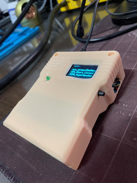
Case
With the cartridge built and configured is now time to print the case. There is a project available on Thingiverse so we can print using a standard 3D printer. Keep in mind that there are two versions of the same case within project files: one is using M2 screws and the second M2.5.
When printing the front face of the case I immediately saw that the case is shorter than the board. It seems it was created for a different PCB version. Another problem is with the original position I soldered the cable connector. It seems the case was created considering that the connector should be soldered on the back side of the board.

The solution I implemented was moving the connector to the back side of the board and remix the case so we can get it 6mm higher. I was included some room to handle the socket I’m using for the EPROM as the original project seemed to support only EPROMs soldered directly to the PCB.
I also didn’t like the way the name/title was included, so I removed to be able to print the case with better quality.

Standard 11mm spaces were used to support the Raspberry PI to the main PCB. Here is the result. Still missing the M2.5 screws.


The STL files for the remix are available on Thingiverse.com here.
Using it
To run the file browser program:
LOAD”FB64”,8
RUN
Or pick the file using the board buttons 2 and 3 to navigate, push button 1 to enter folders and then mount a specific file. Then just load the program using:
LOAD”*”,8,1
RUN
Happy retro computing! 🙂