
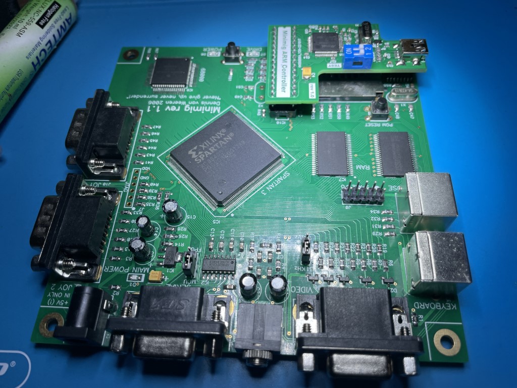
An FPGA-based implementation of the original Commodore Amiga 500 hardware is known as Minimig (or MiniAmiga). Minimig is now available for download as an open-source / open-hardware design with a single 12x12cm PCB with project and assembly instructions published under the GNU public license.
The Minimig assembles all of the Amiga’s parts onto its PCB. It lacks a hard drive and a floppy drive. Instead, it has a floppy emulator and an MMC flash card slot.
The flash card holds the disk-images which can be loaded using an on-screen-display menu.
This document is my attempt to consolidate the very disperse documentation about the minimig and offer a concise guide if you want to build a board. Most of the websites that hosted files required are also offline currently. So I’m building a GitHub repository at
Hardware Description
The original hardware of the Minimig consists of 4 major parts:
- The FPGA
- The 68000
- The RAM
- The PIC controller

The FPGA
The FPGA is the heart of the Minimig. The chip used is a 400K LE Spartan-3 by Xilinx. All the other major components (RAM and 68000) connect directly to the FPGA.
The FPGA implements the Amiga custom chips Denise, Agnus, Paula and Gary as well as both 8520 CIA’s. It also implements a simple version of Amber so that VGA monitors can be connected. Besides this, the FPGA also acts as an automatic joystick-mouse-switcher, a PS2-to-Amiga-keyboard converter, PS2-to-Amiga-mouse converter and as an OSD (on-screen-display) generator. All of these functions were not present in the original Amiga but make life much easier.
The Spartan-3 is a ram-based FPGA and must be loaded with a “core” upon startup. This is done by a PIC controller (or a PIC replacement child board).
The 68000
The 68000 is the Minimig’s main processor. The Minimig uses a special version of the 68000: the MC68SEC000. This version runs at 3.3V and is completely static (so it can run at any frequency between 0 and Fmax). This makes it an excellent companion for the Spartan-3 FPGA as there is no need for level-shifting between 3.3V and 5V levels. The MC68SEC000 connects directly to the FPGA.
The RAM
The Minimig board contains 2Mbyte of 70ns static ram. The RAM is organized as 2x 524288*16 banks. Each bank has separate enablers for the upper and lower byte. The RAM is used to implement the 3 types of memory needed by the Minimig, namely: kickstart rom area, chip ram and (ranger) fast ram.
As the Minimig has no kickstart socket, the kickstart image must be loaded upon startup. This is done by the PIC controller as described below. Once loaded, writes to that area of the RAM are disabled and the area acts like a read-only memory. The remaining part of the RAM (1.5Mbyte) is divided up between chip and fast ram.
The PIC controller
The PIC controller plays the role of BIOS. It is a single chip 8-bit microcontroller from Microchip. The PIC controller configures the FPGA (by loading the Amiga core into it), loads the kickstart image into the kickstart ram area and acts as an Amiga floppy emulator. Thus, the PIC controller really starts the system up as soon as power is applied, hence the “bios”-like function. The Minimig uses a 18LF252/SP PIC controller.
Due to the current challenge to procure those PIC micro controllers, there is the need to look for alternatives. In the project forums an ARM AT91SAM7S256 based controller in a child board was then created. The child board implements the same functions proposed initially for the PIC micro-controller using modern components (still widely available).
These instructions contain the steps required to build the computer using the PIC controller as well as the child board. Detailed info on how to obtain the gerber files and the list of components for it can also be obtained at ARM Controller Nachbau [amiga-wiki] (amigawiki.org) page.
How the Minimig works
Boot Sequence
When the computer is turned on for the first time, it executes the boot sequence. The boot sequence is formed by a two step process:
- The FPGA must be configured first. As previously stated, the PIC controller performs that. Then the Kickstart image must be loaded as the next step.
- Once the FPGA is configured, the system is booted in a special state. In that state, a small boot rom is placed at addresss #0. This boot rom loads the kickstart through the floppy emulator.
Once the kickstart has been loaded, the boot rom then resets the system. The boot rom then disappears from address #0 and the system boots as if it were a normal Amiga.
The code from the boot rom was written in 68000 assembly.
The PIC firmware used to control the initial boot sequence was written in C. The firmware also contains an MMC (Multi Media Card) and FAT16 drivers to control the flash card operation.
User Interface and OSD
The firmware also handles the user-interface and on-screen-display. The PIC communicates with the FPGA through an SPI interface. The MMC card is also connected to this SPI bus. In it’s current form, the FPGA has 2 SPI “addresses”. Address #0 is selected by the fpga_sel0 signal and control the floppy emulator. fpga_sel1 controls the on-screen-display. fpga_sel2 is currently unused.
Kickstart
To function, Minimig needs a kickstart rom image. The Kickstart is a copyrighted. Therefore, you are not allowed to just download it anywhere from the web. You must own the original kickstart rom and make an image of them using the method described in the UAE archives. You can get the Kickstart ROMs buying the Amiga Forever package by Cloanto.
Cloanto offers the only licensed way to pick up the Amiga Kickstart ROMs dumped to a file that can be used with the Minimig.
Building Instructions
List of Components – Main Board
| Qtd | Reference | Value | Description | Link |
| 22 | C5-C8,C16,C18-C19,C21-C22,C25, C28-C30, C35-C36,C39-C40, C43-C44,C46,C52,C55 | 10nF | C805 SMD Ceramic Capacitor | Ali Express |
| 21 | C3,C10-C13,C20,C23-C24,C26, C31-C34, C38,C41-C42,C45,C50, C53-C54,C56 | 100nF | C805 SMD Ceramic Capacitor | Ali Express |
| 2 | C49, C51 (only if using the PIC controller) | 47pF | C805 SMD Ceramic Capacitor | Ali Express |
| 1 | C48 | 100pF | C805 SMD Ceramic Capacitor | Ali Express |
| 1 | C47 | 22pF | C805 SMD Ceramic Capacitor | Ali Express |
| 4 | C4,C17,C27,C37 | 100uF 6.3V | Tantalum Capacitor B-Case | Ali Express |
| 3 | IC1, IC3, IC4 | LM1117MP-ADJ | Adjustable power regulator | Ali Express |
| 7 | R20,R22,R24,R59,R63,R64,R65 | 4K7 | R805 SMD Resistor | Ali Express |
| 28 | R2,R3,R13,R18,R27,R29,R30,R31,R32,R33, R34,R41,R43,R44,R45,R46,R47,R48,R50, R52,R53,R56,R57,R58,R60,R61,R62,R66 | 270 | R805 SMD Resistor | Ali Express |
| 1 | R55 | 1M | R805 SMD Resistor | Ali Express |
| 7 | R7,R9,R11,R28,R54,R67,R68 | 2K2 | R805 SMD Resistor | Ali Express |
| 2 | R25,R26 | 180 | R805 SMD Resistor | Ali Express |
| 10 | R12,R14,R35,R36,R37,R38,R39,R40,R42, R49 | 100 | R805 SMD Resistor | Ali Express |
| 7 | R4,R5,R6,R8,R10,R16,R17 | 560 | R805 SMD Resistor | Ali Express |
| 6 | R1,R15,R19,R21,R23,R51 | 1K | R805 SMD Resistor | Ali Express |
| 4 | C1, C2, C9, C15 | 100uF/16V | Electrolytic Capacitor PTH | Ali Express |
| 1 | C14 | 22uF/16V | Electrolytic Capacitor PTH | Ali Express |
| 3 | D1, D7, D8 | BLUE, RED, GREEN | L805 Led | Ali Express |
| 1 | X1 | 4.433619 Mhz | HC-49S Passive Quartz Crystal Oscillator | Ali Express |
| 1 | X2 (only if using the PIC controller) | 20.000 Mhz | HC-49S Passive Quartz Crystal Oscillator | Ali Express |
| 5 | D2, D3, D4, D5, D6 | BAV99 | Transistor SMD | Ali Express |
| 1 | IC10 Socket | 28 pin narrow | DIP Socket | Ali Express |
| 2 | IC6, IC7 | IS62WV51216BLL TSOP44 II | SRAM (at least 70ns) | Ali Express |
| 1 | Memory Card Connector, MultiMediaCard (MMC) | SDBMF-00715B0T0 | Push-Push, 7 Contacts | Newark |
| 1 | IC8 | 74HC4060 SOP16 | 14-stage binary ripple counter | Ali Express |
| 1 | IC2 | SP3232EUCN SOP16 | 3.3V, 1000 Kbps RS-232 Transceiver | Ali Express |
| 1 | IC9 | MC68SEC000FU20 QFP64 | Micro Processor | Ali Express |
| 1 | J2 | DC-005 | Power Jack Socket DC Connector | Ali Express |
| 2 | J6, J10 | DB9 Male | DB9 Male PCB Mount D-Sub 9 pin PCB Connector | Ali Express |
| 1 | J3 | DB9 Female | DB9 Female PCB Mount D-Sub 9 pin PCB Connector | Ali Express |
| 1 | J1 | P2 3.5mm | Phone Audio Connector, 3 Contacts, Jack, PCB Mount, Metal Body | Digikey |
| 1 | J4 | DB15 Female | DB15 3Rows Parallel Port 15 Pin D Sub Female Plug VGA Adapter | Ali Express |
| 1 | J8 Mouse | Green | PS2 6P 6-pin Connector | Ali Express |
| 1 | J5 Keyboard | Purple | PS2 6P 6-pin Connector | Ali Express |
| 2 | MENU, PGM RESET | 6x6x7 | Push Button | Ali Express |
| 1 | IC10 (*Only if the ARM controller board is not used) | PIC18LF252 DIP28 | PIC Micro controller | Ali Express |
List of Components – Arm Controller Board
The list below is required if you decide to use the ARM controller board instead of the PIC micro-controller.
| Qtd | Reference | Value | Description | Link |
| 1 | U1 | AT91SAM7S256-AU | ARM Microcontroller MCU 256kB Flash 64kB SRAM 55MHz 4 PWM | Ali Express |
| 5 | C3, C14, C15, C16, C17 | 100nF 16V | 0603 10% X7R | Ali Express |
| 2 | C6, C7 | 1uF 6.3V | 0603 10% X7R | Ali Express |
| 2 | C9, C18 | 10pF 50V | 0603 5% C0G | Ali Express |
| 2 | C11, C12 | 15pF 50V | 0603 5% C0G | Ali Express |
| 4 | C1, C5, C8, C13 | 1nF 50V | 0603 5% C0G | Ali Express |
| 1 | C10 | 33pF 50V | 0603 5% C0G | Ali Express |
| 1 | C2 | 10nF 50V | 0603 10% X7R | Ali Express |
| 1 | C4 | 10uF 16V | SMD-B 10% Tantalum | Ali Express |
| 1 | X1 | 18.432MHz | HC49/SM 18.432 MHz | Ali Express |
| 2 | R2, R3 | 27R 0.1W | 0603 1% | Ali Express |
| 2 | R1, R7 | 1K5 0.1W | 0603 1% | Ali Express |
| 1 | R6 | 10K 0.1W | 0603 1% | Ali Express |
| 1 | R5 | 100K 0.1W | 0603 1% | Ali Express |
| 1 | R4 | 1M 0.1W | 0603 5% | Ali Express |
| 1 | Q1 | BC807-25 | BC807-25 transistor SOT-23 | Ali Express |
| 1 | N/A | 2P | 2-Position DIP switch | Ali Express |
| 1 | CN1 | 5-pin | USB mini-B SMD | Ali Express |
| 1 | U2 | 28-pin (2×14) | 28-pin header | Ali Express |
Tips
Although it is generally recommended to solder all difficult parts (like the FPGA, RAM chips and 68000) first, I would like to advise another order of building the Minimig. This alternative order of building will allow you to test a sub-section of the board before soldering the expensive components.
One of the most important parts of the board is the power supply system. So, my recommendation is to build this part first by soldering the following components:
- All 10nF capacitors
- All 100nF capacitors
- All tantalum capacitors (pay attention as they are polarized)
- Power regulators
- Resistors and leds with references R37,R38,R42,R14,R26,R28,R2, and D1
- Electrolytic capacitors and the power plug
Note that if you are using the controller board instead of the PIC controller, you don’t need to solder C49 and C51 as the X2 oscillator is not used by the board, only by the PIC controller. Of course, X2 is not required as well if you decide to use the board. It will be replaced by the 18.432Mhz oscillator that is used on the child board.
At this stage, the power supply can be tested. Double check if all components are soldered correctly (especially the capacitors!) and connect a 5V regulated power supply to J2. D1 should light up blue. Feel if any of the regulators don’t get hot. If all is well, proceed by testing the following voltages:
| Test Point | Voltage |
| Voltage at J6, pin 7 | +5V +/-5% |
| Voltage at J10, pin 7 | +5V +/-5% |
| Voltage at J5, pin 4 | +5V +/-5% |
| Voltage at J8, pin 4 | +5V +/-5% |
| Voltage at tab of regulator IC1 | +3.2V to +3.4V |
| Voltage at tab of regulator IC3 | +1.20 to +1.26V |
| Voltage at tab of regulator IC4 | +2.40 to +2.6V |
Only if all of these voltages check alright you can proceed by soldering the big chips IC5, IC6, IC7 and IC9. Because all SMD parts at the bottom side of the PCB are now soldered, you cannot lay the board flat anymore. Therefore, give the PCB some “feet” before soldering the big chips.
After that solder the remaining SMD parts and finally solder all trough-hole components.
Programming the PIC controller
If you decide to use the PIC controller, and of course if you find it with reasonable prices, that is the only part the needs programming.
The FPGA is configured upon startup by the PIC. This means that you do not need any JTAG cables or special tools to program the Minimig, besides of course a PIC programmer.
Programmers for PIC microcontrollers are cheap and widely available, both as DIY projects or as commercial programmers. The pictures below show two options you can use to program the micro-controller: The XGecu TL866II Universal Programmer (in the picture it is being used to program a GAL, but it also works for the PIC we are using for the Minimig), or the PICkit-2 programmer with the Universal Programmer Adaptor.


You can buy those programmers from AliExpress: PICKit 2 or TL866II.
PIC controllers can only be erased when operated at 5V. The Minimig operates at 3.3V so you would never be able to completely “reset” the PIC when something go wrong with normal computer use. Thanks to the socket soldered to the PCB, the PIC can always be taken out and inserted into a programmer for reprogramming when needed.
Here are the steps to program the PIC micro-controller for the Minimig using the PICkit 2:
- Assuming you will be using the PICkit2 programmer, download the programmer software from the Microchip website and install it on your PC.
- Download the Tiny PIC Bootloader from its page here. We will download the firmware to the PIC controller initially using the programmer and then directly on the board by switching the jumper to MCU.
- Adjust the jumpers on the back of the Universal Programmer Adaptor to program the PIC18LF252 DIP28 micro-controller.
- Connect the Universal Programmer Adaptor to the PICkit 2 and use the USB cable to connect the programmer to your PC.
- Run the PICkit v2 programmer software. If everything is correctly configured, you will see the message saying that the PICkit 2 is connected and the micro-controller will be identified by the programmer.

- Click the Erase button. In a few seconds your micro-controller will be erased by the programmer and you will receive a message saying the process was completed.
- Click File and then Import Hex. Navigate to the folder where you uncompressed the firmware.hex file. Click Open.
- Enable the following fuse bits FOSC2, LVP, FOSC0, /PWRTE, WDTEN
- Click Write.
- After a few seconds you will receive a message saying the programming was successful.

If you are using the TL866II you need to follow the steps below:
- Download and setup the XGPro Software that you can download from http://www.xgecu.com/
- Run the XGPro programmer software.
- Under Select IC, click the button and select the PIC18F252 DIP28 IC from the list.
- Click Load and navigate to the folder where you uncompressed the firmware.hex file. Make sure you select the Intel HEX on File format. Click OK.
- Important!!! Select the tab Config and select FOSC2, LVP, FOSC0, /PWRTE, WDTEN

- Click PROG.
- Select all options on Program Range and hit Program.

- Wait for the programming process to finish.
Programming the ARM Controller Board
If you are following this part of the article you opted by the use the ARM controller board instead of the PIC controller.
The ARM controller has a few advantages over the old PIC option.
- – emulates four floppy drives
- – adds write support to harddrive and floppy disks
- – allow increase of the CPU speed from 7.09 to 49.63 MHz with a 4kb zero waitstate cpu cache
- – allows usage of long floppy file names
- – allows usage of directories on the SD card
- – allows unlimited number of files by directory
- – support for 2 HDF files
- – fast firmware boot
To program the board you will need the SAM-BA in system programmer software by Microship. You can download it from https://www.microchip.com/en-us/development-tool/SAM-BA-In-system-Programmer
Here are the steps to flash the firmware to the ARM controller child board:
- Download and unzip the SAM-BA in system programmer.
- Switch the TEST dip switch to ON (number 1) and power the board.
- Wait 10 seconds and turn off the board.
- Switch the TEST dip switch back to OFF.
- Connect the USB cable to your PC and to the board. Then power the board again.
- Run the SAM-BA (I used the 2.18 version for Windows) and select the COM port that was created when you plugged the board to the PC.
- Select the at91sam7s256-ek board and hit connect.

- Click on the open file icon on the side of the Send File Name text box and select the firmware.bin file from the ASB140501 folder.

- Click Send File.
- Click No on the message asking lock regions.
- Click on Compare sent file with memory. And check if you get a message saying that the content and the memory match exactly.
- Done. You have your board programmed.
Jumpers and SD Card
Make sure you use a jumper to define the video frequency to match your monitor. You can choose between 15Khz or 31Khz. Usually 31Khz offer a more broad range of supported monitors as 15Khz is not quite used anymore in modern displays.
Leave the second jumper on MCU.
If you are using the PIC controller, format the SD Card with FAT and save the appropriate minimig1.bin file to the root. You may choose between a NTSC or PAL configuration and that will determine the file you need to save to the card.
Also save the kick.rom file on the root of the SD card.
Keep in mind that you cannot have a partition with more than 4Gb if using FAT. And it is not exFAT, it is just FAT.
If you are using the ARM controller, then you can format the card with FAT32 and save the files on the root.
First Boot
Turn on the board with the sd card inserted. The default behavior is to flash the drive light quickly as the PIC controller (or the ARM board) configures the FPGA with the minimig1.bin file. Then the kickstart is copied to the memory area where it will be resident and the 68000 starts executing code.
You will see the default kickstart prompt page on the screen after a few seconds.
Did you get blinking codes with the drive light? Please use the below table to decode those.
number of blinks:
1: neither mmc nor sd card detected
2: fat16 filesystem not detected
3: FPGA configuration error (INIT low or DONE high before config)
4: no MINIMIG1.BIN file found
5: FPGA configuration error (DONE is low after config)
6: no kickstart file found
Remember you need to push F12 to open the on-screen-display. You can also use the menu button on the board.
Issues
The first two units built were using the CD4060 integrated circuit as I initially thought they were somehow equivalent to the HCF4060. However when turning on the computer with the CD4060 you can clearly see issues with the synchronization on the image.
When using the CD4060 you will get a blue screen with the lateral suffering for some sort of interference. I ended up figuring our that the CD4060 and HCF4060 are very different. They are both binary ripple counters/dividers integrated circuits (ICs) produced by Texas Instruments, but they differ in a few key specifications.
The CD4060 is part of the CMOS 4000 series and is designed to operate with a supply voltage range of 3V to 15V. It has a maximum clock frequency of 4 MHz, and its typical power consumption is around 10 microamps.
The HC4060 is part of the high-speed CMOS (HCMOS) family and is designed to operate with a supply voltage range of 2V to 6V. It has a maximum clock frequency of 25 MHz, and its typical power consumption is around 2 milliamps.
When replacing the CD4060 by the HC4060 the problem just goes away, so be aware of that if you are building the minimig and make sure you are getting the right ICs for the computer.
Bom dia,,, vc faz sobre encomenda este amiga 500? se sim, ja viria com sd com soft e jogos? obrigado e aguardo
Eu ainda tenho componentes para montar um se você estiver interessado.