
Intro
The WozBlaster OPL4 cartridge is a sound expansion device for the MSX computer platform that provides additional audio capabilities, including support for FM synthesis and sample-based (wavetable) synthesis. It uses the OPL4 (FM Operator Type-L4) YMF-278 sound chip developed by Yamaha that was used in a variety of electronic musical instruments (Yamaha MU5 and TG-100 sound modules, Yamaha Portasound electronic keyboards (PSS-51, PSR-200, PSR-210, PSR-215, PSR-300, PSR-310, PSR-400, PSR-410, PSR-500, PSR-510 and PSR-600), QR-10 music accompaniment player, and QY-20 music workstation) and computer sound cards (Yamaha SoundEdge series).
The cartridge is an external device, clone of another sound cartridge for the MSX called Moonsound and allows access to the capabilities of the OPL4 sound chip from MSX games and general OPL4 compatible music software. The Wozblaster was originally designed by Gustavo Iriarte in Argentina.
As I said before the YMF-278/OPL4 chip offers both frequency modulation and sample-based synthesis. The FM synthesis component is essentially an YMF-262 (OPL3) block; thus, it is also backwards-compatible with the YM3526 (OPL) and the YM3812 (OPL2). Like the OPL3, it can operate in one of four ways:
- 18 two-operator FM channels
- 6 four-operator FM channels + 6 two-operator FM channels
- 15 two-operator FM channels + 5 FM drums
- 6 four-operator FM channels + 3 two-operator FM channels + 5 FM drums
Four-operator FM allows more complex sounds but reduces polyphony, which is the style of simultaneously combining a number of parts, each forming an individual melody and harmonizing with each other.
Eight waveforms are available for the FM synthesis:
- simple sine
- half sine
- absolute sine
- quarter sine (pseudo-sawtooth)
- alternating sine
- “camel” sine
- square
- logarithmic sawtooth
Differently from the OPL3, which has four channels for sound output, the OPL4 features six channels.
The six output sound channels can be sent to an external DAC (usually YAC513) or a digital effects processor (YSS225). Sadly, documentation for the YSS225 cannot be found on-line. The YSS225 is said to perform reverberation, echo, flange and other effects, something not supported by the simple YAC513 DAC.
The sample synthesis part of the OPL4 is based on pulse-code modulation (PCM). It features:
- Up to 24 simultaneous sounds (voices)
- Output sampling frequency of 44.1 kHz (it can also accept 22.05-kHz samples – they are up-sampled to 44.1 kHz before output)
- Waveform data lengths of 8, 12, or 16 bits
- Stereo output (with a 4-bit/16-level pan for each voice)
The PCM synthesizer part accepts:
- Up to 4 MB of external memory for wave data
- Up to 512 samples
- External ROM or SRAM memory. If SRAM is connected, then wave data can be downloaded from the OPL4.
- Chip select signals for 128 KB, 512 KB, 1 MB, or 2 MB memory can be output.
Moonsound clones usually have 1 MB of sample-RAM and have the 2 MB Yamaha YRW801-M General MIDI ROM on board. In fact the board has capacity to address more than 1MB, but the original one had only two 512K memory chips.
The original Wozblaster PCB can’t be fitted into a traditional MSX cartridge case, also as you will see when following the building instructions, the audio jack holes are so small in the original board that we couldn’t find a connector.
Image below features the original Wozblaster:

The reloaded version was then created with the appropriate holes for the Konami as well as the Patola cartridge cases. We also enlarged the holes for the audio jack allowing a most common audio jack connectors to fit.
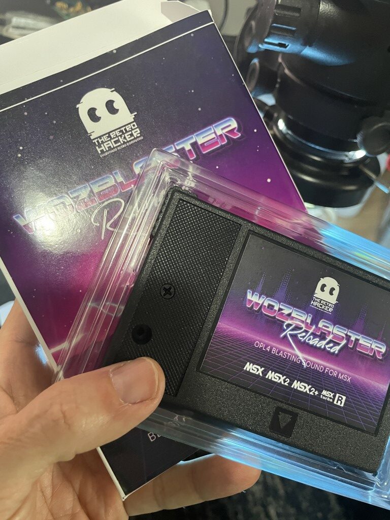
The following image presents the Wozblaster reloaded v1.1:

Architecture and Specifications
Besides the aforementioned components(YMF-278 audio chip and the YAC513 DAC), the cartridge uses two LF347 operational amplifiers made by Texas Instruments. The two amplifiers are connected to the two analog outputs of the YAC513 and connect to a standard 3.5mm audio jack providing stereo sound.
On the digital side, the Moonsound, as well as its clone Wozblaster performs an IO selection on ports 7Eh~7Fh. That task is assigned to the Lattice GAL16V8D SPLD chip that is programmed to implement the logic circuit that are responsible not only for the cartridge selection, but to configure the YMF-278 registers from commands sent by the MSX software.

Here is a list with all cartridge technical specifications:
- Yamaha YMF278B OPL4 sound synthesizer
- 100% OPL1/OPL2/OPL3 compatible (note: the MSX-AUDIO is also OPL1 compatible, so MSX-AUDIO software that doesn’t use the MSX-AUDIO ADPCM part can be used on the OPL4)
- OPL4 has an independent CPU with its own memory so even a slow 3,58 MHz MSX computer is able to replay high quality samples with minimum of CPU power
- Wave table part: 24 PCM channels (stereo: adjustable in 16 steps for each channel; replay frequency up to 44.1kHz)
- Replay of 8-bit, 12-bit or 16-bit data
- Support for 2MB of Sample-RAM for own samples
- FM synthesizer
- 18 2-operator FM channels
- 15 2-operator FM channels + 5 FM drums
- 6 4-operator FM channels + 6 2-operator FM channels
- 6 4-operator FM channels + 3 2-operator FM channels + 5 FM drums
- 2MB wave table ROM (Yamaha YRW-801) with (approx.) 330 samples, mostly 22kHz 12-bit
- Compatibility with the General MIDI standard (128 melody sounds and 47 percussion sounds)
Building Instructions
The cartridge is published as open hardware and can be built by anyone. Here you can find the list of components, instructions to build and links to buy the appropriate components. The instructions can be applied to the original Wozblaster as well as the Wozblaster Reloaded.
List of Components
| Qty | Reference | Value | Description | Link |
| 7 | c13, c16, c17, c18, c19, c20, c23 | 100nF (104) | 50V monolithic ceramic capacitor | Ali Express |
| 2 | c14, c15 | 12pF (120) | 50V monolithic ceramic capacitor | Ali Express |
| 1 | c1 | 10pF (100) | 50V monolithic ceramic capacitor | Ali Express |
| 2 | c4, c11 | 15nF (153) | 50V monolithic ceramic capacitor | Ali Express |
| 2 | c2, c12 | 33nF (333) | 50V monolithic ceramic capacitor | Ali Express |
| 4 | c3, c5, c6, c7 | 2.2nF (222) | 50V monolithic ceramic capacitor | Ali Express |
| 1 | c21 | 4.7uF 16V | Electrolytic Capacitor | Ali Express |
| 1 | c8 | 10uF 16V | Electrolytic Capacitor | Ali Express |
| 2 | c9, c10 | 22uF 16v | Electrolytic Capacitor | Ali Express |
| 1 | c22 | 470uF 16v | Tantalum Capacitor Case D (or E) 477C | Ali Express |
| 8 | R3, R4, R5, R6, R8, R10, R11, R12 | 1K | Carbon (or metal) film resistor 1/4W | Ali Express |
| 2 | R1, R2 | 360R | Carbon (or metal) film resistor 1/4W | Ali Express |
| 2 | R7, R9 | 100K | Carbon (or metal) film resistor 1/4W | Ali Express |
| 1 | R13 | 3.3K | Carbon (or metal) film resistor 1/4W | Ali Express |
| 1 | J1 | PJ-307 | 3.5mm Stereo Jack Audio Connector | Ali Express |
| 1 | Q1 | 33.8688 Mhz | Quartz Crystall Resonator HS-49S | Ali Express |
| 2 | U4, U5 | KM684000ALG | 128Kx8 bit Low Power CMOS Static RAM (SOP-32) | UT Source |
| 2 | U2, U3 | LF347 | JFET-input operational amplifier (SOP-14) | Ali Express |
| 1 | IC2 | YMF278B-F | Yamaha OPL4 sound chip | UT Source, eBay, Ali Baba, or Ali Express |
| 1 | IC3 | YAC513-M | Yamaha Audio Digital-to-Analog Converter (SOP-16) | Ali Express |
| 1 | IC5 | GAL16V8D | SPLD CMOS Generic Array Logic (DIP-20) | Ali Express |
| 1 | IC4 | 27C160 or MX29F1615 | 16 Mbit EPROM/Flash (DIP-42) | Ali Express (27c160) Ali Express (MX29F1615) |
Building tips
Here are a few tips if you decide to move forward and build your own original Wozblaster or the Wozblaster reloaded.
- The holes for the audio jack on the original board are not large enough to support the standard PK-307 connector. If you use a lot of care you can force it through the holes and then solder, but I do recommend the use of a sharpening pen to reduce the size of the connector pins so you can fit it better to the PCB. Please do not attempt to enlarge the holes on the PCB, not a good idea.
- If you don’t plan to enclose the board into a case, use sockets for the 27C160 EPROM (or the MX29F1615) as well as for the GAL. The old 27C160 are tough to program if you don’t have the right programmer and are mega obsolete… that means you will have a high failure rate when programming those and big chance to get it bad sooner than later.
- Start soldering one of the RAMs (left side first) and then test the board with the Moontest tool. You need to pass the test for the first 512K then you can go ahead, solder the second chip and repeat the test before declare the board OK in terms of RAM. I got a high rate of damaged RAM chips from my vendor and the board works ok with just 512K, so you can avoid any possible damage having to de-solder damaged chips from the board.
Programming the GAL16V8D
The GAL16V8D is a programmable logic device (PLD) that can be programmed to perform various logical functions and can be used to implement a variety of digital circuits.
It is used to implement the selection logic on the Wozblaster.
You need to use an TL866 programmer to program the GAL16V8D chip. The TL866 is a universal programmer that is capable of programming a wide variety of devices, including PLDs like the GAL16V8D.
On the project repository you can find the GAL16V8D.jed file that is required to program the chip. Follow the steps below to program:
- Connect your TL866 to your PC, insert the GAL16V8D chip in the programmer ZIF socket and execute the Xgpro app.
- Click the Select IC button and search for GAL16V8D. Click Select.

- Click load and select the GAL16V8D.jed for the Wozblaster.
- Click PROG.
- Uncheck the lock bit option and click Program.

- Wait until the chip gets programmed.

Programming the 27C160 or MX29F1615
The TL866 cannot be used to program the 27C160 or the MX29F1615. It is not just because you can’t find those chips on the list but mainly because those are DIP-42 and the TL866 only offers a ZIF-40 socket. To overcome that issue you can use a specific adapter or a different programmer.
The adapter to allow the TL866 to program the 27C160 can be built using a specific open source project available at mafe72/27c160-tl866-adapter: Adapter to program EPROMs with more than 40 Pins on the TL866 universal programmer. (github.com)
If you choose to follow that path, be aware that you will need a specific software like HJSplit to split the source EPROM file into 512Kbytes parts and then use the 27C4096 DIP40 device on the Xgpro software with specific configuration on the pulse delay to program the chip.
I used the Xeltek Superpro 610P universal programmer to load the software into the 27C160 chip. But before that I had to submit the chips to UV light in order to get them erased appropriately.
Erasing
To erase the chips you need to use Ultraviolet Light UV EPROM erasers available on AliExpress.
According to the 27C160 Eprom datasheet, “The recommended erasure procedure for M27C160 is exposure to short wave ultraviolet light which has a wavelength of 2537 Å. The integrated dose (i.e. UV intensity x exposure time) for erasure should be a minimum of 30 W-sec/cm. The erasure time with this dosage is approximately 30 to 40 minutes using an ultraviolet lamp with 12000 μW/cm power rating.”
As those cheap Chinese EPROM erasers don’t come with manuals, I have no idea on the power rating for the UV lamp, so let’s wait 40 minutes and then test the EPROMs to check if they are all F after the exposure time.

Programming
With the EPROMs erased, we can program them.
Here are the steps to program the M27C160 EPROM using the XELTEK SuperPro 610P.
- Connect the programmer to the PC and execute the SuperPro 610P programmer software.
- Click Device and search for M27C160. Click OK.

- Insert the EPROM to the ZIF Socket and lock it. Note that differently from other programmers, the SuperPro 610P requires the EPROM to be inserted on the lower side of the ZIF socket.

- Click Load file and select the YRW801-M – Yamaha – 1993.rom file. Click OK.
- Click Blank check to ensure you have a blank EPROM.
- If you receive a message saying Blank_Check OK, then move forward with the programming process. Otherwise, use again the UV eraser to make sure you have blank EPROMs.
- Click Program to start the programming process. After a few seconds you should receive a message saying Program OK!.

Tests and Observations
Use the moontest tool to test the board RAM. Run the tool and wait until the test shows passed for all installed RAM chips. As I mentioned before, it is a good strategy to solder just the first RAM chip, test and if everything is OK, move to the next one (testing after). As you can see in the images below I got a lot of problematic chips from my vendor, and you need to have a fully OK test before declare it OK in terms of memory.

The cartridge case
For the original Wozblaster board, the only alternative is a custom made 3D printed case. I created a model and printed a case in black ABS. It is available for you to print on the project GitHub. The case is a bit bigger than the conventional MSX cartridge case and has the four screw holes aligned with the holes on the original PCB.


For the Wozblaster reloaded board, a standard Patola case (although I haven’t tested, a Konami case should fit as well) can be used to enclose the cartridge. You will need to make a hole on the right side of the cartridge using a Dremmel and then put the board on the case.
Here is the final result.

Software
On the Github repo I uploaded a zip file with multiple files to be used with the Moonsound and with the Wozblaster. You can download that file or use any MSX game or software compatible with the card. Please check the URL for the GitHub repository on the resources section.
You can also get additional software for the Moonsound/Wozblaster on the File Hunter MSX repository and checking for OPL4 compatible software at MSX Games World – Search results and Find all your MSX Software, Hardware and Publications on Generation-MSX.nl | Resultaten | Generation MSX
Resources
- GitHub Repository with everything you need to build your own cartridge cristianoag/wozblaster (github.com)
- YouTube video showcasing the cartridge (in Portuguese) https://youtu.be/v7IqDq9fX7o
- Yamaha YMF278 | Sand, software and sound (sandsoftwaresound.net)
- Wierzbowsky/MoonTest: Wozblaster/Moonsound card on-board RAM tester (github.com)
- I/O Ports List – MSX Wiki