
The RBSC MultiMapper cartridge was designed to provide an easy way to load ROMs to the MSX system.
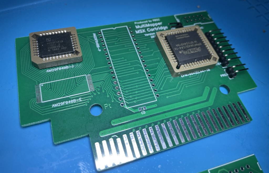
It has the ability to mimic major MSX mappers, such as Konami4, Konami5, ASCII8 and ASCII16. It also has a “planar” mode where data is presented in a 64kb block. The cartridge utilizes an Altera CPLD chip (EPM7064SLC44) and uses a 512kb FlashROM chip (AM29F040). RBSC developed the firmware for the cartridge, which can be updated via the JTAG connector with the help of a USB Blaster programmer.

The cartridge’s advantages include its uncomplicated design (comprising only 2 chips and a few SMD passive components), low-cost production, easy maintenance, versatile configuration options, and reliability. It was designed to accommodate 3 different types of FlashROM chips – TSOP32, PLCC32, and DIP32.
In this article I’ll show the process I used to build one of those cartridges and detail the process to program the CPLD and flash ROM files into the memory.
Bill of Materials
| Part Descrition | Part Name | Part Descrition | Qty | Link |
| U2 | M29F040B | 4 Megabit (512 K x 8-Bit) CMOS 5.0 Volt-only, Uniform Sector Flash Memory | 1 | Ali Express |
| U1 | EPM7064SLC44 | CMOS EEPROM-based programmable logic devices (CPLD) – 5V | 1 | UT Source |
| C1 | TANT-SMD-B-10UF-10V | Tantalum Capacitor SMD Case B 10V 10UF | 1 | Ali Express |
| C3-C7 | 0603-100NF | 0603 100NF Ceramic Capacitor (104) | 3 | Ali Express |
| R1-R4 | 0603-1KR | 0603 1K R Resistor | 4 | Ali Express |
| R5-R9 | 0603-10KR | 0603 10K R Resistor | 5 | Ali Express |
| N/A | MULTIMAPPER-1.0-PCB | PCB Multimapper 1.0 | 1 | JLC PCB or PCBWay |
Building Tips
The process of building is fairly easy. I suggest using sockets as a precautionary measure in case you encounter any issues with the CPLDs. These CPLDs are known to have JTAG pins utilized as IO pins, and this can result in them becoming locked until a programmer is used that can program them through a method other than JTAG.
The Altera CPLDs that were previously used are now outdated, and they can be replaced with the ATMEL ATF1504. Moreover, these Atmel chips can be unlocked using a method that is described in this article: https://www.hackup.net/2020/01/erasing-and-programming-the-atf1504-cpld/.
Also keep in mind that the holes on the PCB are Konami compatible. That means you need to have a case that can fit Konami PCBs.

Programing the CPLD
There are two alternatives to program the CPLD. If you happen to have a universal programmer that is compatible with the Altera old CPLDs used by the cartridge you can program the chips off board and then just solder or install the CPLD on its socket (if you are using sockets of course).
If you don’t have one of those programmers then you will need to use the JTAG connector that is present on the cartridge and perform an on board programming.

To program the CPLD on board, you will need a USB Blaster programmer and a cable to supply 5v to the cartridge board. Follow the steps below to update the firmware:
- Connect +5v to the cartridge board, ensuring correct polarity.
- Connect the USB Blaster programmer to a USB port and wait for drivers to install.
- Launch the Quartus II Programmer software.
- Connect the USB Blaster programmer device to the cartridge, paying attention to the markings on the JTAG connector. Twist the connector slightly for better contact with the board.
- In the Quartus software, select USB Blaster as the default programming device.
- Click “Autodetect” to detect the installed Altera chip.
- Once the chip is detected, move the mouse cursor to the newly-added device string.
- Right-click with a mouse and select “Change File.”
- Select the .POF file containing the firmware data.
- Check the boxes for “Program/Configure,” “Verify,” and “Blank Check.”
- Click “Start” to initiate writing the firmware into the Altera chip.
After the firmware has been successfully written to the chip, disconnect the USB Blaster and the 5v cable from the cartridge. If the chip is not detected, double-check that all cables are connected correctly.
WARNING! Do not attempt to program or update the firmware while the cartridge is inserted into the MSX slot as this could cause damage to both the cartridge and MSX computer.
Flashing
The procedure for writing data to the FlashROM chip is known as “flashing” – and no, it doesn’t involve showing off your chest or biceps. 🙂
First things first, remove the PRG jumper, set both A16 and K4 jumpers, insert the cartridge into the MSX slot, and power on the computer. Setting both jumpers will disable the cartridge and allow the MSX to boot normally.
To program the cartridge, you need to boot into MSX-DOS or MSX-DOS2 and use the FL16.COM utility created by GDX. You can download it from gdx-msx/FL: MSX Rom Loader for MegaFlashRom (github.com).
After booting into DOS, carefully remove the K4 jumper to enable the cartridge’s functionality. Then, use the FL16.COM utility to write any suitable ROM file into the cartridge.
For example, you can use the following command line to start the FL16.COM utility:
FL16 KMARE.ROM
This command will prompt the FL16.COM utility to detect the cartridge, erase the flash chip, and write the file named “KMARE.ROM” into the cartridge. If there are no errors, then the cartridge is ready to be used – much like a pizza delivery guy arriving at your doorstep.

The only thing left to do is set the correct mapper type for the loaded ROM file. For Knight Mare (KMARE.ROM), you’ll need to leave the jumper on A16 and remove K4 – but do this only after powering off the MSX and removing the cartridge from the slot. Finally, set the PRG jumper, and the cartridge is ready for use. Just pop it into any MSX slot and power up the machine.

If the game doesn’t start, check whether the mapper is set to the correct type for the loaded ROM file. If all else fails, blame it on the weather, not the cartridge.
WARNING! Never insert or remove the cartridge from a cartridge slot when the MSX is powered on! Doing so may cause severe damage to your cartridge and/or MSX computer. We don’t want you to lose your superhero powers!
IMPORTANT: The A16 jumper is not only used for setting the ASCII16 mapper, but it’s also necessary for programming any ROM file into the cartridge with the FL16.COM utility. If you set the jumper to any other mapper configuration, the FL16 utility will not work correctly – it’s like trying to brush your teeth with a fork.
Configuration Jumpers
The RBSC MultiMapper cartridge features 5 configuration jumpers that enable the user to customize its operation. The block of 4 jumpers is used to select the operating mode, while the standalone PRG jumper controls access to the FlashROM chip.
Here’s how the configuration jumpers can be used:
- To select the Konami4 mapper, set the K4 jumper and leave the other jumpers unset.
- To select the Konami5 (SCC) mapper, set the K5 jumper and leave the other jumpers unset.
- To select the ASCII8 mapper, set the A8 jumper and leave the other jumpers unset.
- To select the ASCII16 mapper and the default programming mode, set the A16 jumper and leave the other jumpers unset.
- To select planar mode (where only the first 64kb of data is visible), leave all jumpers unset.
- To disable the cartridge (for reprogramming purposes), set any 2 jumpers.
The PRG jumper is used to disable detection of the FlashROM chip. If it’s set, it’s not possible to write any data into the chip. By default, this jumper must be installed to prevent a game written into the FlashROM from being erased or replaced. To enable reprogramming of the cartridge, the PRG jumper must be removed.
Final Result
Here is the cartridge already on its case! Well… we need a label ASAP!

