
When you start expanding your MSX using new feature cartridges, there is a big chance you will end up having to expand the number of your computer physical slots.
There are many options on the market, expanding to 2 or 4 slots and allowing the use of more than two cartridges simultaneously. That makes sense when you are using extension cartridges and not just games, for example you may need a memory expansion and a sound expansion connected to your computer additional to the game cartridge you are using to load your game.
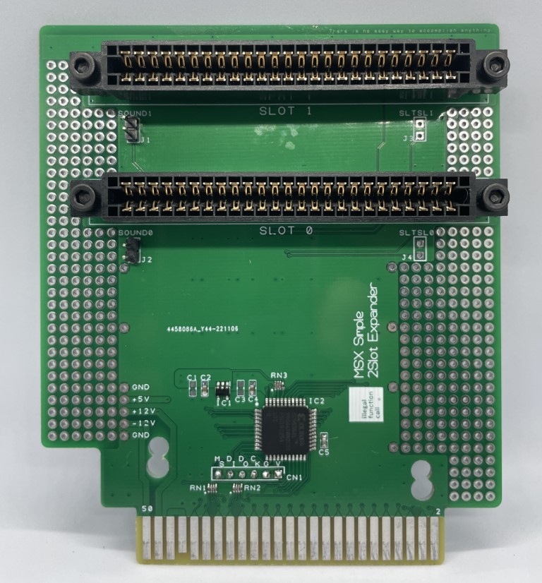
The cheapest and easiest option available is the 2-slot expander cartridge. That expansion complies with the expansion slot specification of the MSX standard and was designed to be as inexpensive as possible by reducing the number of slots and omitting the bus buffer, power supply, and audio mixing circuits required for the expansion slot unit.
This article is documenting all the steps and providing tips and tricks in case you decide to build one.
Important notes
- Due to the lack of a bus buffer circuit, incompatibilities may arise depending on the combination of the MSX and cartridge.
- The power capacity of each slot depends on the MSX computer you are using. It may not work with cartridges with high power consumption. (Up to 5V 100mA by standard)
- The SOUND IN pin is directly connected between the two slots via two jumper sets. Avoid inserting cartridges that use sound output into both slots with jumpers enabled. In the worst case, that can break your cartridge.
- BUSDIR signals are supported.
Board
The board can be manufactured by PCBWay, JLCPCB or any other company in that market. All the Gerber files as well as the code for the Xilinx CPLD used by the expansion cartridge can be obtained on GitHub in the following repository v9938/MSX2SlotExpander: Simple logic 2Slot Expander unit for MSX (github.com)
Bill of Materials
The table below document all the components required to build the slot expansion cartridge.
| Reference | Value | Description | Package | Qtd | Link |
| IC2 | XC9536XL-VQG44C | CPLD – Complex Programmable Logic Devices 3.3V 36-mc CPLD | TQFP-44 | 1 | Ali Express |
| RN1, RN2, RN3 | 4.7K | 0804 0402*4 Network Resistor 4.7K | 0402*4 (0804) | 3 | Ali Express |
| C2 | 4.7uF | 0603 SMD Multilayer Ceramic Capacitor | 0603 | 1 | Ali Express |
| C5 | 0.1uF | 0603 SMD Multilayer Ceramic Capacitor | 0603 | 1 | Ali Express |
| C4 | 1uF | 0603 SMD Multilayer Ceramic Capacitor | 0603 | 1 | Ali Express |
| IC1 | 3.3V | TPS76033DBVT LOW-POWER 50-mA LOW-DROPOUT linear regulator | SOT-23-5 | 1 | Ali Express |
| SLOT0, SLOT1 | 50 pin | Edge Connector Slot 50 Pin PCB with Gold Finger and Mounting ears | 2.54 mm Pitch | 2 | Ali Express |
| J1, J2 | 2 pin | Pin header – single row 90 degree | 2.54 mm Pitch | 4 | Ali Express |
| CN1 | 6 pin | Pin header – single row 90 degree | 2.54 mm Pitch | 1 | Ali Express |
| N/A | 20 mm | Stainless Steel 304 Hex Socket Cap Head Screw | M3 | 4 | Ali Express |
| N/A | M3 nut | M3 | 4 | Ali Express |
C1 and C3 are not connected.
Programming the CPLD
The board uses a Xilinx XC9536XL CPLD that needs to be programmed by a compatible programmer and the Xilinx ISE toolset.
The CN1 pin header is used to connect the programmer to the extender board. Here is a picture on how the cable needs to be connected so you can safely program the CPLD. Note that I soldered the pin header on the back of the board just to avoid having the pins over the components that live on the front.

The board needs to be connected to a power source so you can program the CPLD. To avoid any risks to vintage hardware I’m using an FPGA based MSX to power the board and then program the CPLD. You can use another mechanism to power it during the program phase using the 5V and GND headers on the side of the board. With a pin header installed there you can also provide +-12V to the cartridges connected to the expander.
Here are the steps to program the CPLD:
- Power the board with 5V. Run ISE and open the EXT_SLT project that is available on the CPLD folder on the project GitHub. You may need to download the content of the repo to your local machine.

- Right click Implement Design and select Rerun All. Wait until the finish of the process.

- Double click Manage Configuration under Configure Target Device.

- When ISE iMPACT loads, select Edit and click Launch Wizard. Click OK to automatically connect to the chain.

- At this point you need to have the CPLD recognized by iMPACT.

- Click Yes on the message to assign the configuration file and navigate to the folder where the EXT_SLT.jed file was generated. Click Open.

- Make sure the CPLD is being shown under Boundary-Scan and click OK on the Device Programming Properties window.

- Now you can right click the CPLD representation and select Program.

- After a few seconds executing the command you will receive a Program Succeeded message.


- Done! You have your CPLD programmed and can disconnect the programmer from the board and use the expansion cartridge.
Usage
In my experience, cartridges that also expand the slots for the MSX need to be connected on the traditional slot and not via expander. You can use the expander to connect video cartridges (like the V9990 TRH9000, GFX9000, etc), game rom cartridges and even sound cards assuming you are providing the appropriate +12v/-12v (if required).

As previously said, all jumpers on the board are already connected. If you need to isolate the soundin signal or the slot select signal you need to cut the copper trail on the back of the cartridge and use physical jumpers if those signals are required again.
Avoid using two cartridges that generate sound at the same time, you may have conflicts as both will generate signals on the same trail.
Here is a screen shot of my FPGA MSX without the slot expander.

And now a screen shot of the same MSX with the slot expander

- All my ROM cartridges ran normally from the expanded slots.
- The Carnivore2 cartridge booted on the expanded slot, but it didn’t add additional memory (mapper) and only worked with basic functionality, including flashROM and the sound expansions. That is mentioned on the cartridge documentation: “So, when Carnivore2 is used in such slots, it will no longer work as multi-functional device. Only one of the internal devices will be able to function: FlashROM, FMPAC, RAM or IDE controller.” Moving the cartridge to the primary slot does the trick and it can be used without any issues with all features. Below you can see a screenshot of the slot configuration with the Carnivore2 inserted (booted with the default slot configuration).

- Booting the Carnivore2 from the extended slot I managed to run games from the FlashROM menu without any issues (using the default configuration).
- The SDMapper v1 doesn’t add additional mapped RAM to my MSX neither execute the BIOS to load from the inserted SD cards. When looking the slot configuration with the cartridge attached to a expanded slot we see the following organization (picture below). As you can see the cartridge is not even detected.

- SDMapper v2 works ok to load software from the SDCards, but not expanding memory via its mapper. Here is a picture of the slot configuration with the SDMapper v2.

- V9990 based cards like the TRH9000 and GFX9000 work ok from the expanded slots. In fact I noticed that IO cards like the Obsonet, MSXUSB and others all work ok from the expanded slots.
- Brazilian MEGARAM cartridges don’t work when used from the slot expander (at least not the one present in the SDMapper v1). I haven’t had the chance to test with the real MEGARAM cartridge.
