
Intro
iBolit is a diagnostic cartridge designed to address a common issue faced by MSX users over the years. Many users have reported incidents where their computers cease to function after removal from storage or following a power cycle, experiencing problems such as black screens or complete power failures.
To tackle these issues, the RBSC crew created the iBolit, drawing inspiration from the renowned Doctor Aybolit. Utilizing GAL22V10 programmable logic chips, LED assemblies, and volt/ammeters sourced from USB socket tester dongles commonly used in PCs, the RBSC team engineered a diagnostic cartridge that simplifies the initial check of a computer and eliminates common problems.
The cartridge features a slot on its board, allowing users to insert various cartridges, including those with MSX diagnostics ROM. The GAL firmware, while basic, proves effective: when a high level is detected on the input, the corresponding LED illuminates.
iBolit stands as an affordable and user-friendly solution, providing MSX users with a valuable tool for the initial diagnosis of their computers, helping them identify and address prevalent issues.
Bill of Materials
The table provided below offers a comprehensive bill of materials necessary for constructing the iBolit cartridge. For the fabrication of printed circuit boards, any specialized company can be engaged by utilizing the Gerber files accessible on the project’s website at https://github.com/RBSC/iBolit/tree/master/Gerber.

Please be aware that it may be necessary to compress all files into a zip format before transmitting them to your selected PCB manufacturer.
| Reference | Value | Description | Qty | Link |
| IC1-IC4 | SOCKET-DIP-NARROW-24 | DIP Socket Narrow 24 pins | 4 | AliExpress |
| IC1-IC4 | GAL22V10D | High Performance E2CMOS PLD Generic Array Logic | 4 | AliExpress |
| N/A | CS2510BGYR | LED Bar graph display Light 10-segment | 4 | AliExpress |
| N/A | USB-TESTER-MOD-BLACK | 5V 12V USB Tester LED Digital Voltmeter Ammeter – Black Model | 3 | AliExpress |
| N/A | LED5MMR-RED | Led 5mm PTH Red Rounded | 1 | AliExpress |
| N/A | LED3MMS-RED | Led 3mm PTH Red Squared | 1 | AliExpress |
| N/A | PH-254-D-M-40-RA | 2.54mm 2 x 40 Pin Male Double Row Pin Header Strip Black Right Angle | 1 | AliExpress |
| N/A | PH-254-D-F-40-RA | 2.54mm 2 x 40 Pin Female Double Row Pin Header Strip Black Right Angle | 1 | AliExpress |
| N/A | PH-254-S-M-40 | 2.54mm 1 x 40 Pin Male Single Row Pin Header Strip Black | 1 | AliExpress |
| RN1-RN | 0603X4-1KR | 0603*4 8P4R 2*4P Network Resistor SMD | 12 | AliExpress |
| C5 | 1210-47UF | 1210 47uF Ceramic Capacitor | 1 | AliExpress |
| C6-C9 | 1210-10UF | 1210 10uF Ceramic Capacitor | 4 | AliExpress |
| C1-C4 | 0805-100NF | 0805 100nf Ceramic Capacitor | 4 | AliExpress |
| MSX SLOT PLACEHOLDER | EDGE-50P-90 | Edge Card Connector PCB Gold Finger 50 Pin Right Angle 90 degree | 1 | AliExpress |
| N/A | U1B1212S | DC-DC POWER CONVERTER 1W U1-B1212S | 2 | AliExpress |
| R1 | 0805-2.2KR | 0805 2.2KR Resistor | 1 | AliExpress |
| R2 | 0805-1KR | 0805 1KR Resistor | 1 | AliExpress |
Building Process
The iBolit comprises two PCBs. The primary board, which is larger in size, is designed to be inserted into the MSX SLOT and houses the GAL chips and LED bars. Meanwhile, the secondary board is tasked with reading the computer’s voltages.
Main Board
I recommend starting with the 1K resistor arrays located on the back of the board. It’s important to note that depending on the LED color, you may need to opt for lower resistances. Since I have multicolored LEDs and only 1K resistor arrays available, I chosen to use the 1K ohm resistor arrays. Soldering these first is advisable, as the LED bars will limit the space for maneuvering the soldering iron on the back of the cartridge once they are in place.

The next step involves soldering the 100nF capacitors, the larger 1210 47uF capacitor, and the sockets for the GAL22V10D.


Moving on to the LED bars, pay careful attention to their correct orientation, as LEDs have polarity. In my case, I had multicolored LED bars from a previous project (Spectrolizer). After testing with a multimeter, I determined that the writing on the LED bars indicates the anode (+) side. Remember to trim the long legs of the LEDs after soldering.


The power LED can now be soldered, just before proceeding to solder the EDGE slot for the cartridge. This sequencing provides more space to solder the LED. Be mindful of the polarity; the flat side on the silkscreen represents the cathode (-).

In the top left corner of the cartridge, solder a double male pin header cut as 2×5, as shown in the picture below.

At this point, you should be able to connect the cartridge to your MSX and boot it without encountering any issues. If your computer fails to boot, carefully inspect the cartridge for bridges and shorts, especially on the resistor arrays. Verify if the power LED is lit, and there shouldn’t be any additional activity in other LEDs besides the power LED.

Scondary Board
First step is to setup the three 5V 12V USB Tester LED Digital Voltmeter/Ammeter modules so we can use them on the cartridge. We need to remove the plastic box used by the module as we will use just the PCBs.


Now using the hot air, remove the USB connectors from both sides and make sure the 7 segment displays are correctly aligned with the PCB. You can also use a solder sucker to remove the connector and resolder the display. I prefer to use the hot air station for that. You may need to use your solder iron to fix the solder joints or appropriately clean the soldering holes appropriately.


Cut segments of 4 pins on the 2.54 single male pin header and solder the small measurement PCB boards into the secondary iBolit board.
One of the USB measurement modules will be used to represent the -12V and will need a led to indicate the negative. We will solder a squared led to represent that. You will need to correctly solder the LED considering the cathode (-) and the anode (+). With the 7 segment display on the right, the cathode will be soldered on the superior track and the anode on the second pin from top to down.

Now we need to install two U1B1212S power converters. We need to fold the legs in the way they can be installed correctly on the board. Chheck the picture below to better understand how to fold the pins and solder the converters.


Still on the back side of the board we need to solder a 2.2K ohm resistor and four 10uF ceramic capacitors.
Basic Test
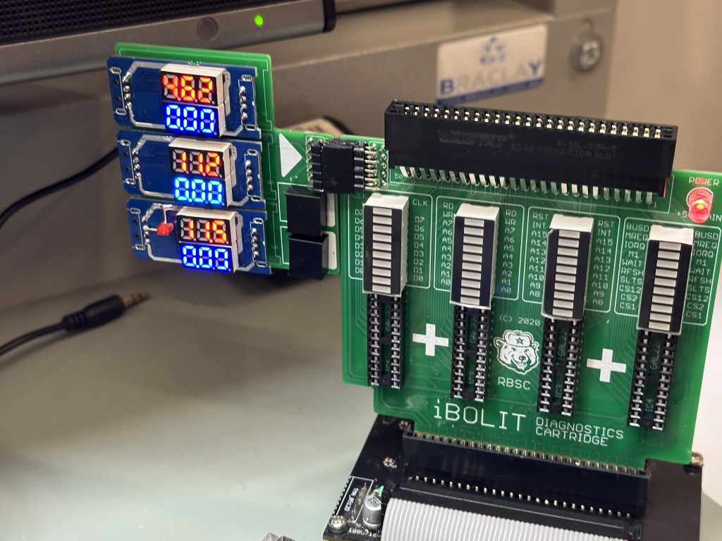
So far we are good to test basic things with the cartridge. Connect the secondary board to the main board and inser the cartridge to your MSX. You should see the voltage indicators showing numbers for the 5V rail as well as -12V and 12V.


Programming the SPLDs
It is time to program the SPLDs (GAL22V10D). You will need a TL866II programmer (or compatible) and the JED file available on the iBOLIT GitHub repository here iBolit/Firmware at master · RBSC/iBolit · GitHub.
Use the XGPro (or equivalent) program to load the file and program the chips. You need to program the same JED file into all four chips. Then insert then to the approriate sockets on the cartridge. Please pay attention to the chip orientation.

You may need to bend the IC pins if they are brand new. I use a simple 3D printer tool to make sure they fit correctly into the sockets.
Tests
Now you can insert the cartridge to one of the slots on your MSX and turn it on. You will see some activity and data being transferred on the bus represented by the different LEDs on the bars. You will also see the voltages on the secondary board.
If you insert a cartridge on the edge slot on top of the cartridge you will see even more activity as just after loading and executing the BIOS, the computer will load the cartridge ROM data and execute the program.

