
Looking for cool projects to use with my MSX (and other vintage computers) I found the TZXDuino. It is basically a small board that combines the Arduino, a micro SD card slot and a phone jack to play digital copies (TZX files) of tapes and load programs on those computers.
I’m specially interested in the Edu Arana’s TZXDuino Reloaded available here. That version uses the Arduino Nano and SMD components to build the capability to load and play TZX, CAS, TSX and other files for the ZX Spectrum, MSX, Amstrad and other vintage computers.
Decided to build one for me and play with it using the retro computers. As usual I’m documenting all the steps taken to build and configure it here so others can use.
The PCB
This time I went a step further and asked PCBWay to build a nice black version of the board. As usual I had to buy 5 and now I have 4 additional boards laying around here (let me know if you need one!). 🙂

As you can see the board is based on surface mounted components and for those of you looking for a project to improve soldering skills from through-role components to SMD this is a great project.
The Arduino Nano board is soldered on the left side of the board and it is used to power the circuit. There is also the option to install a dedicated USB connector on the top right corner, something I’ll not do in my build.
The board also uses a 744050D logic chip and a LM386M amplifier that is activated/deactivated by a SMD switch that is installed on the bottom right corner of the board.
The rest of the components are the 0805 SMD capacitors, leds and resistors as well as the two jacks dedicated to the sound output and remote.
We also have holes to mount a OLED 0.96 128×64 display and places for the micro SD slot and control buttons (located on the top of the board).
Here is the complete Bill of Materials for reference:
| Part | Value | Package | Link to Buy |
|---|---|---|---|
| ACT | RED | CHIP-LED0805 | AliExpress(*) |
| C1 | 100nf | C0805 | AliExpress(**) |
| C2 | 100nf | C0805 | (**) |
| C3 | 10uf | C0805 | (**) |
| C4 | 47nf | C0805 | (**) |
| C6 | 100nf | C0805 | (**) |
| C5 | 220uf (ECA-0JM221) | CPOL-EUE1.8-4 (only with amp) | AliExpress |
| IC1 | 4050D | SO16 | AliExpress |
| IC4 | LM386M-1 | SO08 (only if amp required) | AliExpress |
| POWER | MICRO-USB-B | (or connect directly from Nano) | Optional |
| PWR | GREEN | CHIP-LED0805 | (*) |
| R1 | 10R | R0805 | AliExpress(***) |
| R2 | 330R | R0805 | (***) |
| R3 | 330R | R0805 | (***) |
| R5 | 1k | R0805 (adjust to your needs 1k-10k) | (***) |
| S1 | SWITCH-DPDTSMD | AYZ0202 | AliExpress |
| SD1 | TF-HOLDER | TF-PULL | AliExpress |
| X1 | STEREOJACK 3.5mm | STX3100 | AliExpress |
| X2 | STEREOJACK 2.5mm | PJ-204B | AliExpress |
| PLAY | PUSH BUTTON | B3F-31XX | AliExpress(****) |
| DOWN | PUSH BUTTON | B3F-31XX | (****) |
| ROOT | PUSH BUTTON | B3F-31XX | (****) |
| STOP | PUSH BUTTON | B3F-31XX | (****) |
| UP | PUSH BUTTON | B3F-31XX | (****) |
| M1 | ARDUINO NANO | AliExpress |
All Gerber files needed to manufacture the board are available on Edu’s GitHub here. You can just download the zip file and use the PCBWay website to order.
Build Process
To install the SMD components I used a Yaxun 902+ hot air station and unleaded solder paste. I just placed a small amount of paste in the cleaned contacts and used the hot air gun with 30% adjusted flow to heat the pads.
The solder paste is great to kind of “glue” the SMD components to the board and avoid to have them flying around when the air flow starts.
After some time (and some mistakes – I lost one of the LEDs) here is the result.

The hardest part is definitely the micro SD slot. The contacts are super tiny and you cannot use the hot air gun the same way you use with the other components. There are parts in plastic to hold the card in place that just melt down if you use the hot air. I ended up using the solder iron with care and checked a few times to remove all solder bridges.
I used two rows of header pins to prepare the Arduino Nano for soldering.


To test the whole system and replace components if needed I decide to use a piece of a 8 pin socket to connect the OLED screen. After validate the whole circuit and ensure everything is working ok I’ll use stands and solder the screen to the board just above the chips. Here is the board with the Arduino and the part of the socket already soldered.


Software
During the build I found out that there are basically two versions of the “firmware”. Those are actually Arduino sketches that implement all the functionality. The ArduiTape version, that is managed by Duncan Edwards is available here (note that at the time of this writing the link on Edu’s page is broken).
The version I’m using in my build is the MaxDuino, maintained by Ricardo Molina and available on GitHub here (beta and version archives here).
To use the MaxDuino implementation just clone the GitHub repository in your PC, install the required libraries and upload the code to the Arduino Nano using a micro USB cable. Here are the steps you need to use:
- If required install the Arduino IDE using the Microsoft Store. Just run the Microsoft Store and search for Arduino.
- Connect a micro USB cable to the Arduino and plug it to your PC.
- Open the Arduino IDE and configure the board. As I’m using an Arduino Nano clone, I selected the Atmega328P (Old Bootloader) option and selected COM3. You may need to use other COM ports depending on your configuration.

- Click on the Tools menu and select Manage Libraries, install the SDFat (1.1.4), and SoftI2CMaster (2.1.7). Ensure you are using the versions I mentioned in the parenthesis. I tried with a new SDFat version and got errors (had to roll back).
- Click File, Open and then navigate to where you cloned the GitHub repo. Select the MaxDuino_v1.XX.ino. In my case I initially installed the 1.75 version, so my file was MaxDuino_v1.75.ino.
- You will see all the tabs that form the solution. Go to userconfig.h and change the first line according to the configuration you are using for the Arduino board and the OLED screen. In my case I’m using an Arduino Nano with the OLED1306_128_64, 0,96″. So the option is 7. the first line of my userconfig.h file is the following:

- Now verify and upload the sketch.
The board will boot and you will see a message saying No SD Card displayed on the OLED screen.
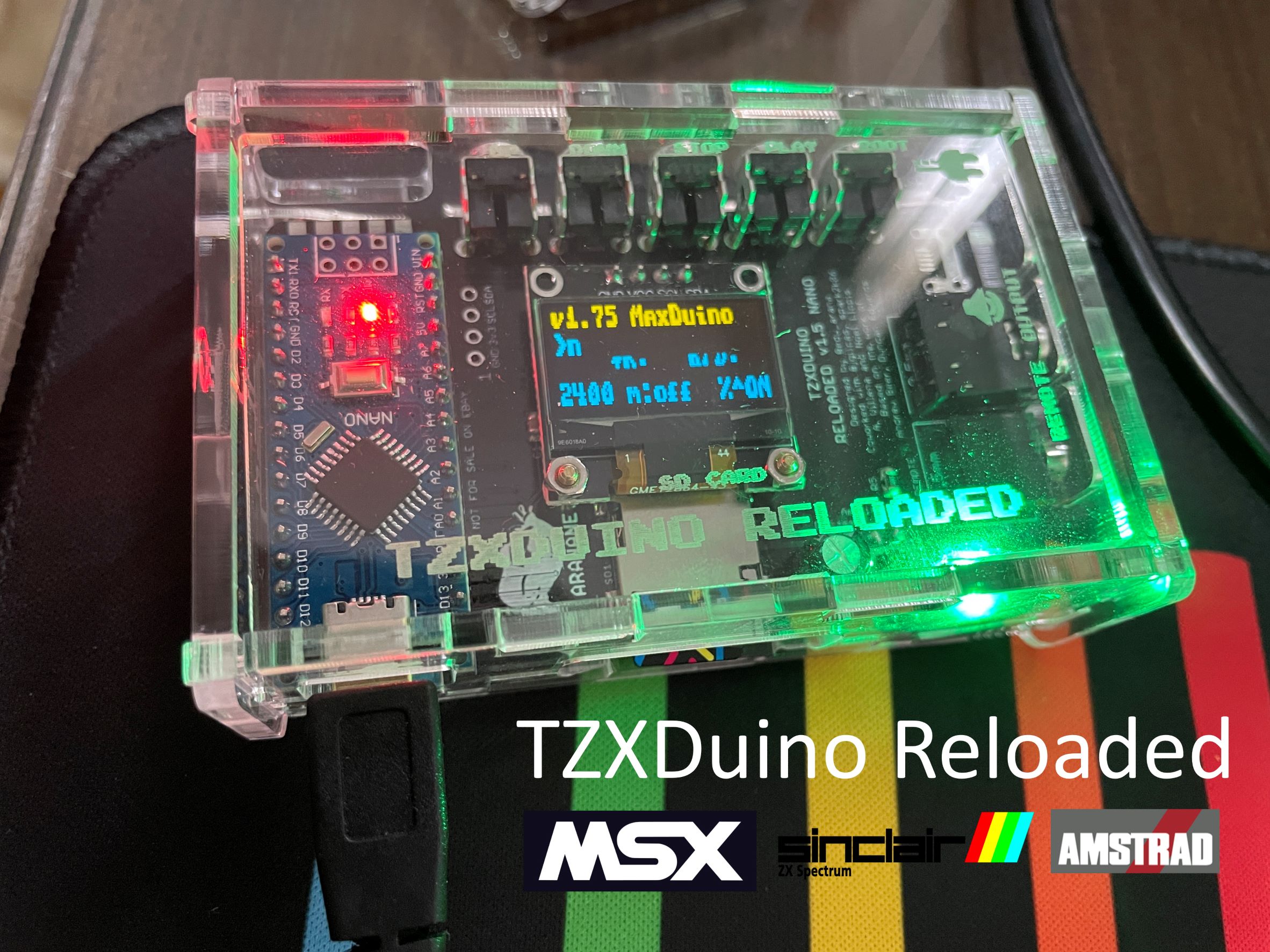
Final Product
Here are a few pictures of the final product already with the acrylic box available on Thingiverse here.


References
Here is the list of references and websites I used to build the TZXDuino:
- TzxDuino-Reloaded 1.5 Nano by Edu Arana – https://github.com/arananet/TzxDuino-Reloaded
- ArduiTape/CasDuino/TZXDuino- The Cassete Player Replacements – http://arduitape.blogspot.com/
- Arduitape Facebook Page – https://www.facebook.com/Arduitape
- MaxDuino Official GitHub Repo by Ricardo Molina – https://github.com/rcmolina/MaxDuino_v1.75
- MaxDuino Beta and Archives – https://github.com/rcmolina/MaxDuino_BETA
- MaxDuino Forum – https://www.va-de-retro.com/foros/viewtopic.php?t=5541&start=9999
- Online calculator – 3 digit capacitors – http://kiloohm.info/3-digit-capacitor/106
- Online calculator – 3 digit SMD resistors – http://kiloohm.info/smd3-resistor/683
- Online calculator – 4 digit SMD resistor – http://kiloohm.info/smd4-resistor/6802
Thanks for this glorious article. Also a thing is that nearly all digital cameras come equipped with the zoom lens so that more or less of that scene for being included by means of ‘zooming’ in and out. These kinds of changes in focusing length are usually reflected while in the viewfinder and on big display screen at the back of any camera.
Hola Eduardo, estaría interesado en saber el precio de la placa TZXDuino Reloaded y los componentes smd, podrías facilitarme un correo donde solicitarte el precio?
No los vendo. Necesitas seguir las instrucciones disponibles en Github y ordenar el PCB y los componentes.