
A few months ago I was browsing aleatory looking for MSX related projects and found a very interesting Spanish website called “Vaderetro (Satanas)”… something like “go to hell, devil” in a very “colloquial” way. Strange name, but awesome content if you like retro computers and can use the Spanish translator provided by your browser… not my case as I speak fairly good (at least in my opinion 😊) Spanish.
Inside the forum, there is a group for open source hardware projects and a conversation topic about a cool project named uMSX. Here is the link if you are interested uMSX: Clon MSX2+ FPGA – Va de Retro (Satanás) — Versión 3 SSL (va-de-retro.com)
I tried to create an account on the page and give my contribution, but at the moment of this writing new user accounts are not allowed there. 🙄
The uMSX project

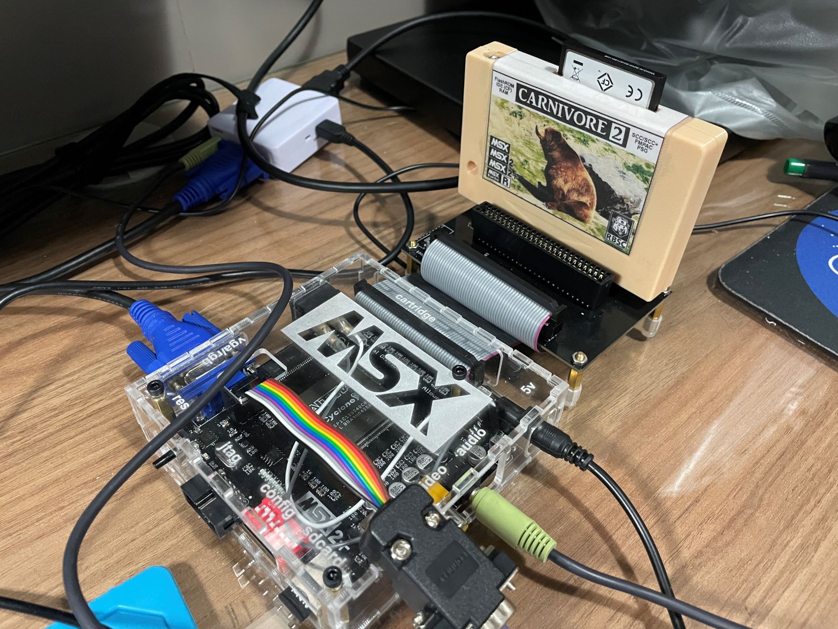
The uMSX is a MSX2+ FPGA implementation that basically mimics the Zemmix (one of the first FPGA based MSX2+ one chip MSX computers commercially available).
The computer PCB project was created by a user (well as the image below mentions, he as a “demon of the third order”) codenamed BCH.

The VHDL code used is the well known KDL PLD implementation for the MSX2+ used by the vast majority of the FPGA based MSX computers known. The uMSX uses the first generation of the KDL VHDL source, also known by esemsx.
Based on the already obsolete (but relatively easy to find) Altera EP1C12 FPGA (specifically the EP1C12Q240C8N), the uMSX uses SMD based components (and a few PTH) in a nice compact form factor. It uses the 4 megabit EPCS4 active serial configuration flash memory to host the firmware and configure the FPGA chip at each time the circuit turns on.
A MT48LC16M16A2 SRAM chip offers memory for the computer, which also uses a few other components to implement the clock logic (NC7WV04P6X inverter and 21.47727 basic PTH crystal oscillator) and a 953B voltage detector and reset IC.
Heavily based on 0603 SMT resistance arrays, and other 0805 SMT components, the uMSX is a compact little OCM MSX that can be used to evolve your SMD soldering skills, challenge your knowledge of modern electronics applied to retro computing, and give you a lot of fun through the journey.
I’m documenting all the steps taken to build an uMSX device in this article.
Parts and PCB
All Gerber files required for PCB manufacturing are available on the forum discussion. There are two zip files containing the main board (version 3.5 at the time of this writing) and the cartridge auxiliary board. I ordered PCBs with the default options and with the stencil, as I used a hot plate to solder most of the SMD components to the board. Copies are also available on GitHub with the rest of the files for the project here.

The following table has the list of all components required to build the main board and the cartridge extension board. Please use the links provided just as reference for the component, those are (for the vast majority) the ones I used to purchase my components.
Main Board
| Qtd | Part | Value | Package | Type | Link |
|---|---|---|---|---|---|
| 1 | uMSX main board PCB | NA | NA | NA | Main Board |
| 1 | Custom acrylic box | NA | NA | NA | Acrylic Box |
| 3 | Nylon pcb standoff | 20mm | M3 | Black | AliExpress |
| 7 | Nylon screw | 10mm | M3 | Black | AliExpress |
| 2 | R106, R96 | 10R | M0805 | SMD Resistor | AliExpress |
| 1 | R113 | 22R | M0805 | SMD Resistor | AliExpress |
| 2 | R4, R6 | 100R | M0805 | SMD Resistor | AliExpress |
| 1 | R7 | 1M | M0805 | SMD Resistor | AliExpress |
| 2 | R8, R10 | 10K | M0805 | SMD Resistor | AliExpress |
| 3 | R13A, R13B, R122 | 1K | M0805 | SMD Resistor | AliExpress |
| 26 | RN133, RN97-101, RN103, RN105, RN108, RN110, RN112, RN114-121, RN123, RN126-127, RN129, RN131, RN135, RN152 | 100R | 0603×4 CAY16 | SMD Resistor Array | AliExpress |
| 8 | RN95, RN107, RN109, RN124, RN128, RN130, RN132, RN134 | 200R | 0603×4 CAY16 | SMD Resistor Array | AliExpress |
| 5 | RN16, RN111, RN125, RN12, RN13 | 1K | 0603×4 CAY16 | SMD Resistor Array | AliExpress |
| 1 | RN94 | 10K | 0603×4 CAY16 | SMD Resistor Array | AliExpress |
| 1 | C1 | 2.2uf | C0805 | SMD Ceramic Capacitor | AliExpress |
| 23 | C3-10, C13-15, C21, C23-25, C30-33, C35-37, C134 | 100nf | C0805 | SMD Ceramic Capacitor | AliExpress |
| 2 | C18-19 | 27pf | C0805 | SMD Ceramic Capacitor | AliExpress |
| 8 | C26-28, C18-19, CI10-11, CI16 | 220uf 10V | 153CLV-0605 | SMD Electrolytic Capacitor | AliExpress |
| 1 | C34 | 4.7uf | C0805 | SMD Ceramic Capacitor | AliExpress |
| 9 | LED1-9 | Any color | CHIP-LED0805 | SMD LED | AliExpress |
| 1 | 12V | 1×2 | 12v pin to the cartridge board | Pin Header | AliExpress |
| 1 | JP1 | 2×5 | joystick connector | Pin Header | AliExpress |
| 1 | JP2 | 1×2 | on/off switch | Pin Header | AliExpress |
| 1 | JP3 | 2×25 | cartridge board connector | Pin Header | AliExpress |
| 1 | JP4 | 2×5 (10 pin) | JTAG | Box Header Connector | AliExpress |
| 1 | JP5 | 3.5mm | Stereo | Audio Jack | AliExpress |
| 1 | PS2 | 6P | keyboard connector | PS2 | AliExpress |
| 1 | Q1 | 21.47727 | HC49/S | PTH Crystal Oscillator | AliExpress |
| 1 | U1 | EPCS4N | 8-pin SOIC | Active Serial configuration flash | AliExpress |
| 1 | U2 | 953BFP | 8-pin SOIC | Voltage detector and reset | AliExpress |
| 1 | U$1 | EP1C12Q240C8N | 240-Pin PQFP | Cyclone FPGA | AliExpress |
| 1 | J1 | Micro SD Slot | AliExpress | ||
| 1 | J2 | DC-005 | Right Angle | Barrel Power Jack | AliExpress |
| 1 | IC1 | MT48LC16M16A2 | TSOP54-400 | SDRAM | AliExpress |
| 1 | IC2 | 3.3v AMS1117 | SOT223 | Voltage Regulator | AliExpress |
| 1 | IC3 | 1.5v AMS1117 | SOT223 | Voltage Regulator | AliExpress |
| 1 | IC5 | NC7WZU04P6X | SOT65P210X110-6AN_SC88_SC70-6 | Dual Unbuffered Inverter | AliExpress |
| 1 | RCA | AV-8.4-5 | RCA | RCA Connector | AliExpress |
| 1 | F1 | 1.1A | 1812 | PPTC Fuse | AliExpress |
| 1 | EDG-08 (SWITCH) | 8 switches | AliExpress | ||
| 1 | S1 (Button) | 6x6x7 | Push/Tactile | Reset Button | AliExpress |
| 1 | VGA | DB15 | FEMALE SHORT | RIGHT ANGLE | AliExpress |
| 1 | ON/OFF switch | 2 pin | 21×15 | Boat switch | AliExpress |
| 2 | Jumper wire | Female | 10cm | ON/OFF cables | AliExpress |
| 2 | Spade Crimp Terminals and Sleeves | Female | 4.8mm | (Buy the set) | AliExpress |
| 1 | Socket Connector | Female | 2.54MM Pitch | Joystick cable connector | AliExpress |
| 1 | Flat Ribbon Cable | 10P (10 pins) | Joystick cable | AliExpress | |
| 1 | DB9 male connector | 9 pin | Joystick cable connector | AliExpress | |
| 1 | microSD/TF card | 4GB | Memory card | AliExpress |
Cartridge Board
| Qtd | Part | Value | Package | Type | Link |
|---|---|---|---|---|---|
| 1 | uMSX cartridge board PCB | NA | NA | NA | Cartridge Board |
| 1 | TMA_0512D | 12V | AliExpress | ||
| 2 | Inductor | 100uf | PTH | AliExpress | |
| 2 | Electrolytic Capacitor | 10uf/25V | 153CLV-0605 | SMD | AliExpress |
| 1 | Electrolytic Capacitor | 100uf/16V | 153CLV-0605 | SMD | AliExpress |
| 3 | Ceramic Capacitor | 100nf | C0805 | SMD | AliExpress |
| 2 | Ceramic Capacitor | 4.7uf | C0805 | SMD | AliExpress |
| 2 | Resistor | 2K | M0805 | SMD | AliExpress |
| 1 | Main board connector | 2×25 | Pin Header | AliExpress | |
| 2 | Edge card connector | 50P | Cartridge | AliExpress | |
| 4 | PCB metal standoff | 15-20mm | M3 | Standoff | AliExpress |
| 4 | Silicone cap | 13mm | M3 | Sleeve/cap | AliExpress |
| 4 | Nut | M3 | Nut | AliExpress | |
| 1 | Main board cable | 20cm | 50P 2x25P | Flat cable | AliExpress |
From the whole list of parts the only challenge is the NC7WV04P6X inverter. Due to the chip shortages caused by the COVID-19 pandemic, multiple orders I placed for that component were cancelled. The vendor which the link I included on the table was the only one actually able to fulfill the order.
Besides the list of components you will also need a PS/2 keyboard, a VGA cable (and possibly a VGA to HDMI adapter), and a 5V 2A power supply.
Soldering SMD components
As the uMSX main PCB has most of the SMD components in just one of the sides, I strongly recommend the use of the stencil and a hot table (or oven) to bond the components to the PCB pads. You will need to use solder paste, flux and patience to position all the components and then carefully check on the microscope or with magnifying lenses to be sure there are no bridges. Specially on the FPGA and with the large amount of really small resistor arrays.
If you are adventurous and want to manually solder, start by the FPGA and make sure there are no shorts/bridges before moving to the other components. It is a lot easier to find solder problems when you have just the FPGA soldered to the board.
As a tip if you are soldering manually, just after finishing with the FPGA chip, check if each leg is fixed to its respective pad. Then look for bridges and remove them. When you are sure that the FPGA chip is correctly soldered to the board, use a multimeter to measure the resistance between the ground and 3.3V on the AMS1117 3.3V regulator (the two legs on the left – check the image below). You should get something from 1.6K to 2K ohms. If you get low resistance (something close to 100 ohms), check again if you have your FPGA correctly soldered.

NEVER turn your board if you have low resistance between the two first legs of the AMS1117 3.3V. Usually the AMS1117 1.5V has much lower resistance, but in the 3.3V line resistance is high.
The heat gun can also be used for the soldering job, just make sure you use the appropriate configuration for the air flow, otherwise you will have SMD components flying around your workbench.
The back side of the main PCB needs to be manually soldered, but there will be just a small number of capacitors a few resistors.
Connectors, slots and PTH components
That is the easiest part. After spending time soldering (or verifying) SMD components, PTHs are a breeze.
Firmware
The firmware for the uMSX is based on the first generation esemsx VHDL/Verilog code. You can download the latest packages from KDL page here, or get the latest development versions directly from his GitHub here.
If you are downloading from the page, you will need the OCM PLD Pack file. Download it and unzip its content in a local file on your PC. If you decide to use GitHub, clone the repository to your PC.
After the unzip, go to the latest version folder and navigate to esemsx3 folder. Check the README file, you will see that you need a pretty old Quartus II version (v11.0 SP1). That is because you are using an obsolete Altera FPGA chip that cannot be programmed by recent versions of the software.
Scrolling down on KDL page you will see a link to download the right version of Quartus. Download and install it.
Note: I had issues with driver certificated for the USB blaster after installing this old version of Quartus. My USB blaster stopped working as the certificates for the driver in v11 are already expired. I reinstalled Quartus 20.1 after and everything worked fine.
Follow the instructions on the README file to compile the VHDL files and program your FPGA. Make sure to follow the instruction to convert the programming file and incorporate the emsx_top_304k.cof file, that way you will have an MSX computer with the EPBIOS. Those steps ensure that you will have the basic BIOS together with the programming file stored on the EPCS4, that will be useful in case you have any issues with the microSD card slot.
Connect your USB Blaster cable and use the Quartus programmer tool to upload the programming file to the EPCS4 flash.
When you turn on your uMSX after assembling the PCB, all LEDs should lit. During programming they will flash, turn off and after boot, the uMSX will flash the last LED indicating it is loading the program to the FPGA chip, then it will lit only the LEDs that are correspondent to the configuration on the DIP switch bank.
Turn on 2 and 3 to have a 30Khz video and the last one (8) so you enable the SD card. If you need to understand what each dip switch does, check those files: DIP-SW User Manual or Zemmix Manual.
The microSD card
The micro SD card can be created using an additional package that is also available on KDL webpage. You will need the file named OCM-SDBIOS Pack. To get it, you will need to click the link and send an email to KDL. He will reply back providing the URL from where you download the file.
Unzip its content and follow instructions on the README file to create your microSD card. If you need additional help, check the below video where I’m showing how to create a microSD card to boot Nextor and use multiple partitions created on the card.
Power Source and Cables
The power supply is a standard 5V 2A center positive.
The joystick cable converts the 2×5 pin header connector of the PCB into a male DB9 connector so you can connect a standard MSX joystick. You can build your own cable using appropriate connectors for both sides and a 10pin flat cable.


The following pictures have the joystick connector pinout on the main board and the pinout for the MSX joystick.


The cartridge board cable is a standard 50P 2x25P flat cable. I used 30cm cables, but found smaller ones could be better. We don’t need such long cables. I ended up folding the cable in order to keep the cartridge PCB closer to the main board.

Case options
There are multiple case options for the uMSX. BCH and others on the forum have published STL files with designs that can be 3D printed. I opted for an acrylic case that can be manufactured in 3mm acrylic. It is a simple box design with the MSX logo and a few indications for the multiple connectors for the board.

I’ve collected all the cases I found on the Github repo for the uMSX.
Troubleshooting
The electronic schematics for the main board is available on the forum, but for specific parts you should also use the Zemmix schematics. Both are available on the GitHub repo I created for the project under the schema folder.
Another thing that was very useful was the Kicad 6 Gerber editor. I used it to find out specific trails and follow how they were connected. You can load the Gerber zip package into the viewer and select the “Show in Differentiation Mode” under view. That way you will be able to better see the layers and understand more about the boards.


Black Screen when booting
Two places to look for problems. The SRAM can have soldering problems or you may have the 200R/100R resistor arrays located closer to the electrolytic capacitors with bridges or even disconnected. Use a microscope or magnifying lenses to check for issues.
The cartridge board doesn’t work
Check the 100R resistor arrays located closer to the cartridge board connector. Bridges or disconnected pads can cause issues with cartridges not recognized. You can also use the carttest.bas tool to check on signals related to cartridges.


Using an oscilloscope you can also check for signals on the cartridge connector. Good thing is all signals are active in low and the initial status is usually high for all signals. You should see 3.3V in most of them and consistent activity 0/3.3 in data and address signals.
The image is missing red, blue or green colors
Check the 200R and 100R resistor arrays located closer to the electrolytic capacitors. They are in the RGB lines and if one or two are disconnected, the color signals are affected. Bridges on those arrays can also cause color problems or even the lack of image.
References
uMSX: Clon MSX2+ FPGA – Va de Retro (Satanás) — Versión 3 SSL (va-de-retro.com)
cristianoag/uMSX: Files to build, program and test the uMSX FPGA MSX2+ clone (github.com)
KdL Index! (gnogni.altervista.org)
Use of the CMOS Unbuffered Inverter in Oscillator Circuits (ti.com)
Olá,
Estou criando coragem para montar também esse projeto, apesar de já ter um MSX 1 Expert. Esse partlist ainda é valido em 2023? O que foi montado nesta página é o mesmo que aparece no vídeo do youtube?
Obrigado
Sim. É o mesmo do vídeo. A lista ainda é válida.
I tried to program the board but I get the error in Quartus ´Can’t recognize silicon ID for device 1´.
I programmed the zemmix and the carnivore 2 in the past and never come across this problem.
I´m using the file ´recovery.pof´ in ocm-pld v3.9.1 zemmixneo_br_layout\single_epbios_zemmixneo_backslash.
Does anaybody know what the problem could be and what I need to check?
Hi Gregory, use the files available on the esemsx3 folder. Make sure to follow the instruction to convert the programming file and incorporate the emsx_top_304k.cof file, that way you will have an MSX computer with the EPBIOS. Those steps ensure that you will have the basic BIOS together with the programming file stored on the EPCS4, that will be useful in case you have any issues with the microSD card slot.
The “Can’t recognize silicon ID for device 1” error message may also indicate that your FPGA is not good. Check if you have any shorts on the decoupling capacitors on the back of the board. Also make sure there are no shorts between legs on the Altera.
I checked the voltages on the board:
MT45LC16M16A2 …. 3,2 V
NC7WZU04P6X …….3,11V
953BFP …………….4,8V
EPCS4N …………….3,2V
What is odd is if I touch the GND pin of the EPCS4N with the GND pen of the Fluke meter, the upper led goes out.
Check for shorts on the 100nf capacitors located at the back of the PCB. If you’re receiving correct voltages yet encountering difficulty programming the EPCS4, it’s probable that the Altera chip is faulty. A malfunctioning FPGA can result in shorts across those capacitors. Additionally, one of the LEDs serves to indicate the synthesis load on the FPGA. Therefore, the blinking LED you observe likely corresponds to this indicator.